Network and Peripheral Cables
Not sure you’re ready?
Take the ~3-minute readiness diagnostic and see where you stand.
The invisible infrastructure of modern human civilization relies entirely on the successful transport of electrons and photons through carefully engineered conduits. Before a cloud service can launch, before a distributed database can synchronize, and before an end-user can load a simple web page, physical impulses must travel across physical media. For an IT professional, mastering this physical layer—the intricate ecosystem of network and peripheral cables—is not merely an exercise in memorization. It is the fundamental grammar of troubleshooting. If the physical layer is compromised, no amount of software configuration will bring the system online. We must understand exactly how we confine, direct, and protect these signals against interference, distance, and environmental hazards.
When we transmit data over copper wires, we are pulsing electricity. Anytime electricity moves through a wire, it generates an electromagnetic field. If two wires are placed next to each other, their fields interfere—a phenomenon known as crosstalk.
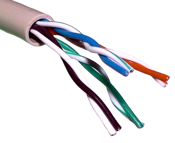
To solve this, engineers use twisted pair cabling. Twisting the internal copper wires in network cables reduces crosstalk between adjacent wire pairs because the opposing electromagnetic fields cancel each other out. The tightness and consistency of these twists define the cable's category and speed capabilities.
UTP vs. STP Cabling
In most office environments, technicians deploy Unshielded Twisted Pair (UTP) networking cables, which lack a protective metallic foil layer. UTP is flexible, inexpensive, and perfectly adequate for standard indoor distances where electromagnetic interference (EMI) is minimal.
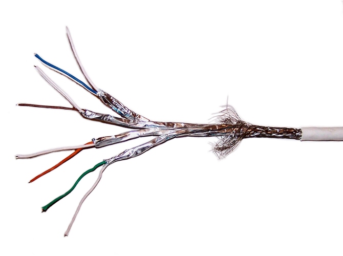
However, in industrial environments with heavy machinery, fluorescent lighting, or high-voltage power lines, UTP fails. The ambient EMI disrupts the data signals. Here, we must use Shielded Twisted Pair (STP) networking cables, which include a protective foil layer to prevent electromagnetic interference. This metallic shield acts as a Faraday cage around the twisted pairs, absorbing ambient interference and shunting it to ground so the internal data signals remain pristine.
Wiring Standards: T568A and T568B
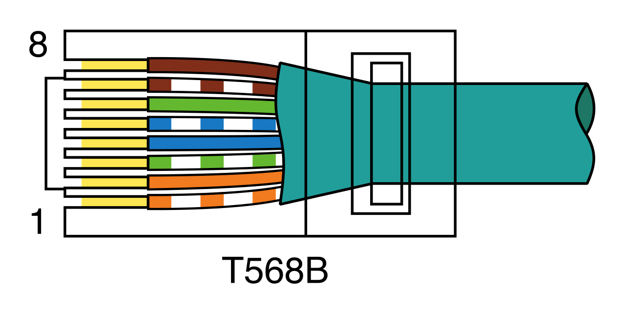
At the ends of these cables are 8-pin RJ-45 connectors. The order in which the colored wires are pinned into these connectors is strictly governed by standards. The two primary color-coding standards are T568A and T568B. They dictate the precise sequence of the eight individual wires.
- The T568A wiring standard terminates pin 1 with a white-green wire.
- The T568B wiring standard terminates pin 1 with a white-orange wire.
Note on Commercial Deployment: T568B is the predominant standard in the United States commercial sector. As an IT technician, you will almost exclusively encounter T568B when punching down jacks or crimping cables.
Straight-Through vs. Crossover
How you terminate the two ends of a cable determines its function.
- A straight-through network cable uses the exact same wiring standard on both ends of the cable. (e.g., T568B on End 1, and T568B on End 2). These are patch cables. You use them to connect different types of devices together, such as a computer to a network switch.
- A crossover network cable uses the T568A standard on one end and the T568B standard on the opposite end. Historically, if you wanted to connect like devices (a computer directly to another computer, or a switch to a switch), you needed a crossover cable to correctly route the transmit pins on one device to the receive pins on the other.
If you are a modern IT technician, you might rarely need to craft a crossover cable. Why? Because modern Ethernet devices use the Auto-MDIX feature to automatically detect and reconfigure crossover or straight-through cable connections. The network interface card algorithmically determines what is connected and flips the transmit/receive logic internally, allowing a standard straight-through cable to work for almost any scenario.
Before twisted pair dominated the local area network, there was coaxial cabling. Today, coaxial remains the backbone of the telecommunications industry's edge network—bringing broadband from the street into the building.
Coaxial cables contain a single central copper conductor surrounded by an insulating layer and a braided metallic shield. This thick, robust design provides exceptional protection against EMI and allows for high-bandwidth frequency multiplexing over long distances.
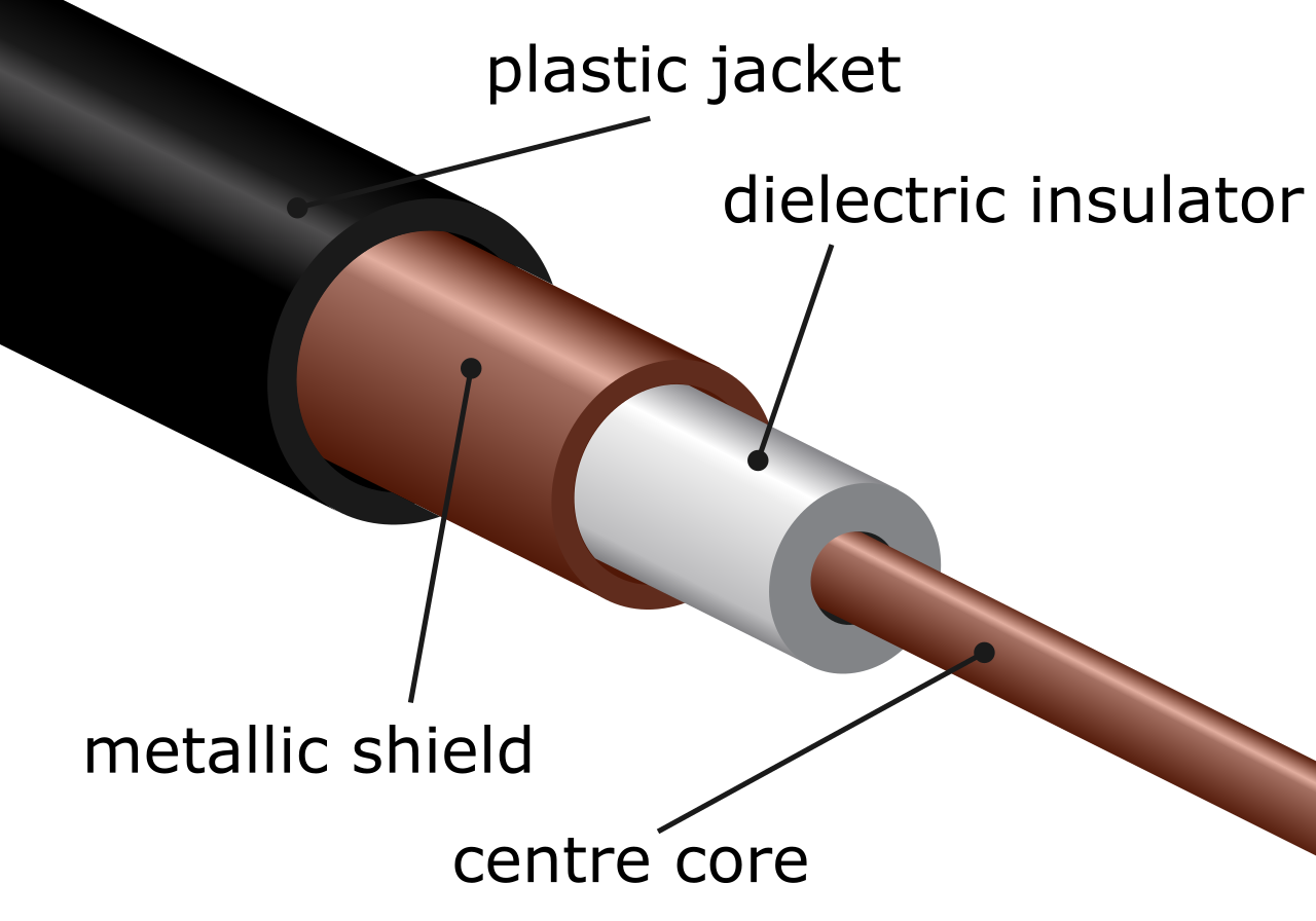
There are two primary variants you must recognize:
- RG-6: These coaxial cables are heavily utilized for television and cable broadband internet installations. When the local ISP runs a line into a customer's modem, they are pulling RG-6. It has a thicker conductor suitable for long-range transmission.
- RG-59: These coaxial cables are typically deployed for short-distance video applications such as analog closed-circuit television systems. It has a thinner conductor and experiences signal degradation over long distances, making it ideal only for localized, baseband video (like a security camera wired to a DVR in the next room).
Coaxial Connectors
You can easily identify coaxial cables by their distinct physical terminations:
- F-type connectors feature a threaded design and are commonly used to terminate RG-6 coaxial cables. This is the classic screw-on connector found on the back of every cable modem and television set. The threaded connection ensures it will not easily pull out if the cable is tugged.
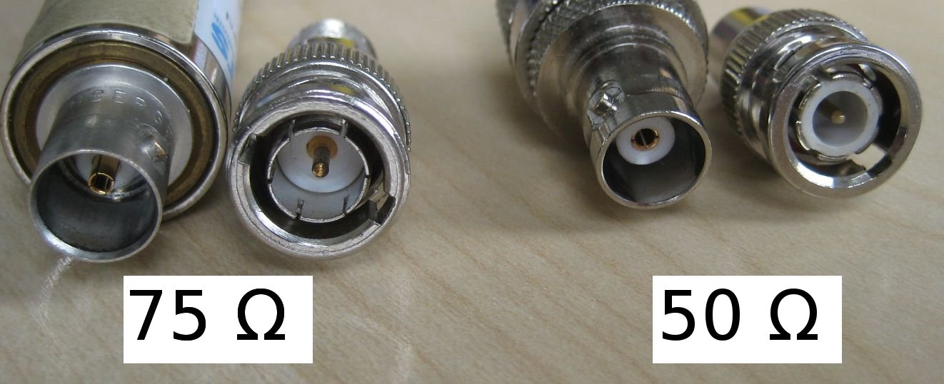
- BNC connectors utilize a push-and-twist bayonet locking mechanism for terminating coaxial cables. Used heavily in professional AV environments, testing equipment, and security cameras (often with RG-59), the BNC connector allows a technician to lock the cable in place with a quick quarter-turn.
Where copper hits physical limitations regarding distance and speed, we turn to photonics. Fiber optic cables transmit data using pulses of light traveling through highly engineered glass or plastic cores. They are entirely immune to electromagnetic interference.
Single-Mode vs. Multimode Fiber
The behavior of the light depends on the thickness of the glass core:
| Fiber Type | Core Size | Light Source | Range & Application |
|---|---|---|---|
| Single-mode | Narrow glass core | Laser | Single-mode fiber optic cables utilize a narrow glass core to transmit a single laser light path. Because the core is so narrow, light travels straight without bouncing off the walls, preventing signal dispersion. Consequently, single-mode fiber optic cables are explicitly designed for long-distance data transmission across multiple miles. They are the backbone of transoceanic internet links and city-to-city ISP routing. |
| Multimode | Wider glass core | LEDs (Light-Emitting Diodes) | Multimode fiber optic cables utilize a wider glass core to transmit multiple light paths using light-emitting diodes. Because the core is wider, light rays bounce off the internal cladding at different angles. This causes signal degradation over long distances. Therefore, multimode fiber optic cables are typically deployed for short-range communication within a single building or campus environment. |
Fiber Optic Connectors
Fiber terminations require extreme precision. A misaligned glass core will scatter the light, causing catastrophic packet loss. You must recognize three common fiber connectors:
- ST (Straight Tip): Straight Tip (ST) fiber connectors utilize a bayonet-style push-and-twist locking mechanism. It looks visually similar to a miniature BNC connector.
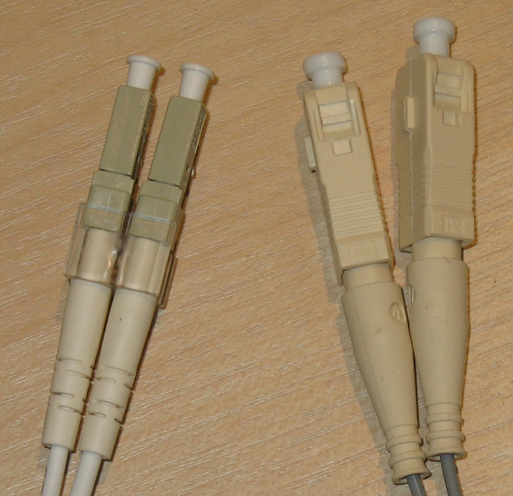
- SC (Subscriber Connector): Subscriber Connector (SC) fiber connectors utilize a square push-pull latching mechanism. You push it straight in until it clicks, and pull it straight out.
- LC (Lucent Connector): Lucent Connector (LC) fiber connectors utilize a small form-factor retaining tab mechanism similar to an RJ-45 plug. Because of its compact size, it is overwhelmingly the standard for modern high-density network switches.
As an IT professional, pulling cable isn't just an exercise in networking; it is an exercise in life safety. Above the drop-ceiling in a modern office, there is an open space where the building's HVAC system pulls return air. This space is called the plenum.
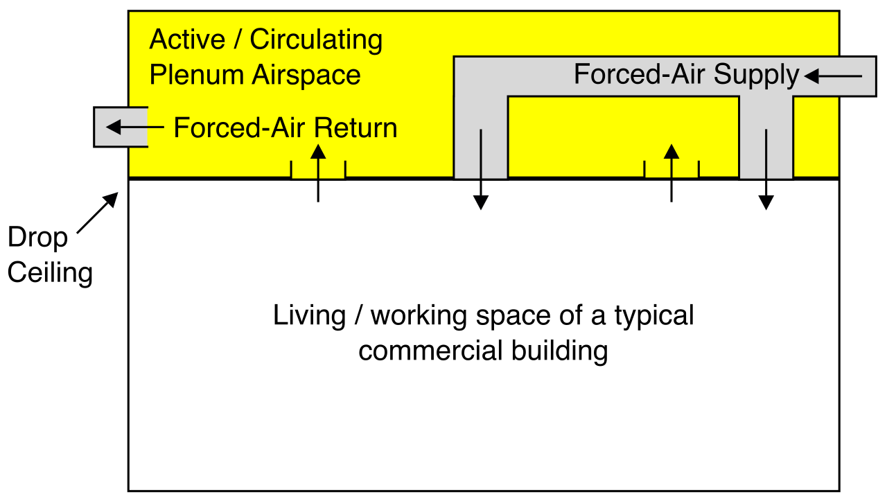
Standard Polyvinyl Chloride (PVC) network cables produce highly toxic fumes when exposed to fire. If a fire breaks out and burns standard PVC cables located in the plenum space, the HVAC system will instantly suck those highly toxic fumes and distribute them into every office in the building. Because of this fatal risk, Polyvinyl Chloride (PVC) cables are strictly prohibited by building codes in building air circulation spaces.
Instead, we must use plenum-rated cabling. Plenum-rated cables are explicitly designed for safe installation within the air circulation spaces of commercial buildings. To achieve this, plenum-rated cable jackets utilize materials like Teflon to minimize toxic smoke production during a fire. They are more rigid and more expensive than PVC, but legally mandated for safety.
For the desktop support specialist, managing the "last foot" of connectivity—the peripheral cables on the user's desk—is a daily reality.
The Evolution of USB
The Universal Serial Bus (USB) revolutionized peripheral connectivity by standardizing what used to be a chaotic mess of proprietary ports. The speeds dictate what kind of peripherals you can reasonably support:
- USB 2.0 cables support a maximum theoretical data transfer rate of 480 Megabits per second. This is sufficient for keyboards, mice, and basic document printing.
- USB 3.0 cables support a maximum theoretical data transfer rate of 5 Gigabits per second. This leap in bandwidth made external hard drives and high-resolution webcams viable.
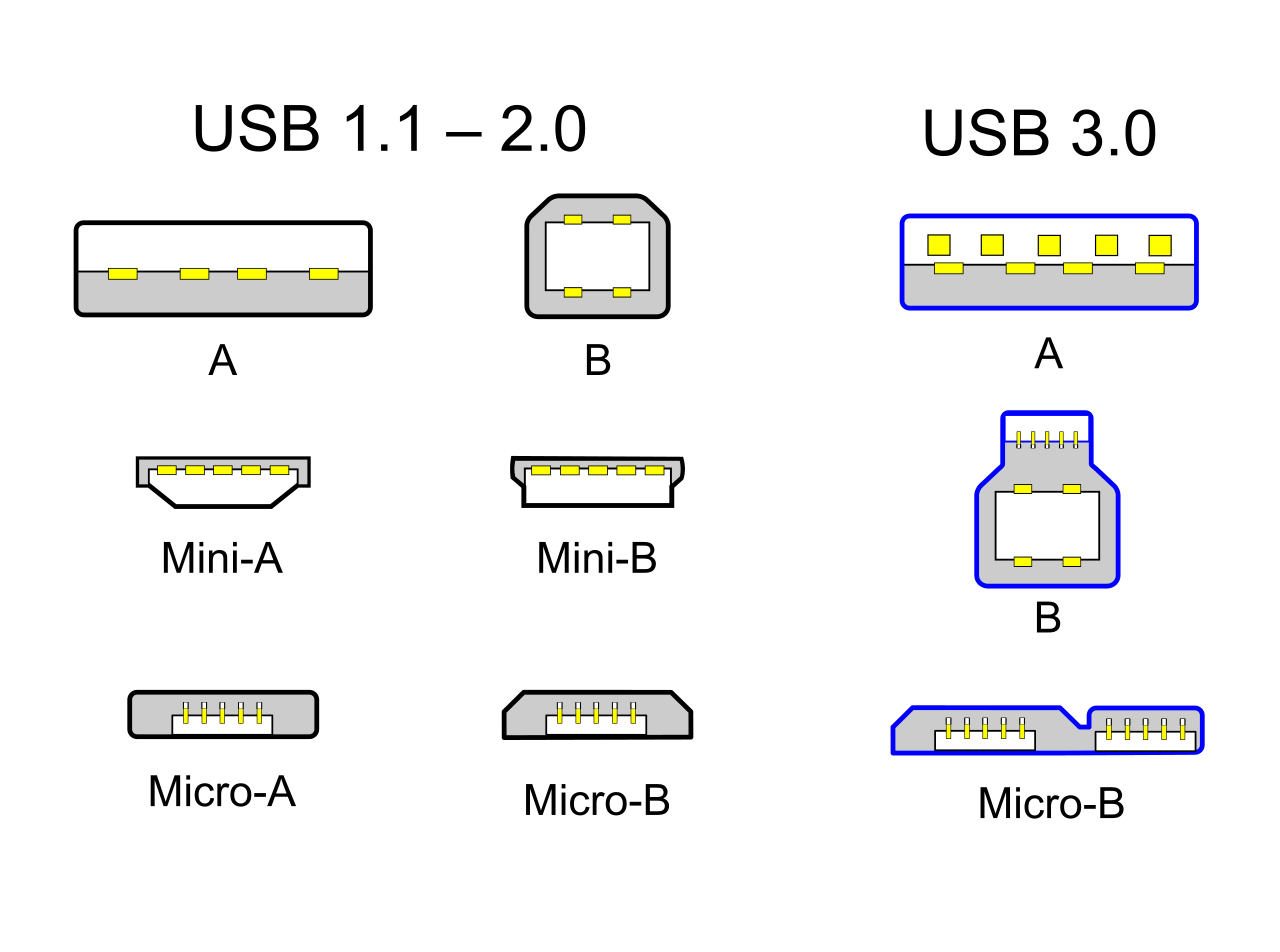
USB connector shapes historically dictated the flow of data, ensuring users didn't accidentally connect two host computers together:
- USB Type-A connectors feature a flat, rectangular shape and plug into host devices like desktop computers.
- USB Type-B connectors feature a square shape with beveled top corners and plug into peripheral devices like printers.
- Mini-USB connectors are smaller than standard USB connectors and are frequently found on older digital cameras.
- Micro-USB connectors feature a flat design with slightly beveled edges and were standard on early Android smartphones.
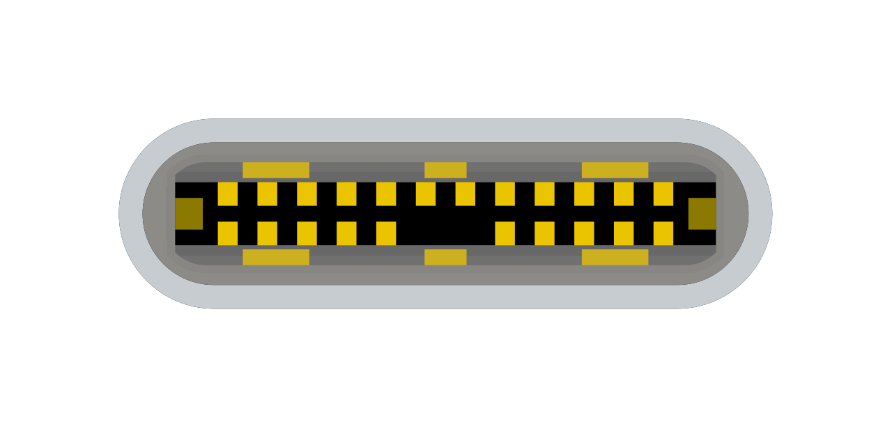
The modern solution to this geometric headache is USB-C. USB Type-C connectors feature a reversible design that allows the plug to be inserted right-side up or upside down. It serves as both a host and peripheral connector, standardizing the entire ecosystem.
Serial Cables: The Administrator's Lifeline
While USB dominates the consumer space, enterprise networking equipment still relies on one of the oldest standards in computing: serial communication.
Serial cables transmit digital data sequentially one bit at a time over a single communication wire. This lack of complexity makes serial incredibly resilient. The RS-232 standard formally defines the electrical signals and voltage levels for serial communication cables.
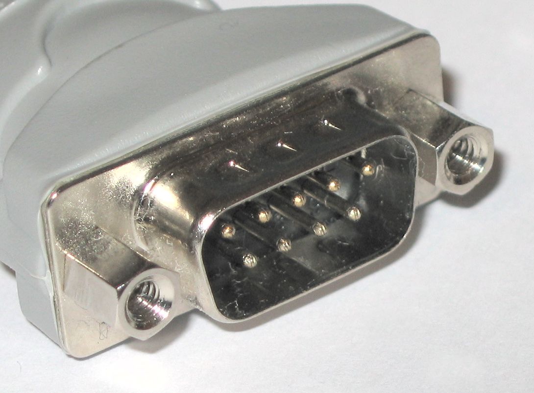
To physically interface with RS-232, we use a distinct connector: DB-9 connectors are 9-pin D-subminiature physical connectors commonly used for serial communication.
Why do we care about a slow, ancient standard? Because when a core network router crashes and falls off the IP network, you cannot SSH into it. The only way to command the device is directly through its hardware layer. Network administrators frequently utilize serial cables to connect a computer to the management console port of a router or switch, allowing out-of-band management to resurrect a dead network.
Thunderbolt: The Convergence Protocol
Finally, we arrive at the pinnacle of peripheral cabling: Thunderbolt. Originally developed by Intel and Apple, Thunderbolt isn't just a data cable; it is a convergence technology. Thunderbolt cables can simultaneously transmit data, video signals, and electrical power over a single connection. This allows a single cable to connect a laptop to an external monitor, charge the laptop's battery, and connect to a high-speed external RAID array all at once.
The standard has evolved through specific hardware iterations:
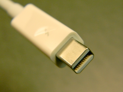
- Thunderbolt 1 and Thunderbolt 2 cables utilize the Mini DisplayPort physical connector shape.
- Thunderbolt 1 cables support a maximum data transfer rate of 10 Gigabits per second per channel.
- Thunderbolt 2 cables aggregate two data channels to support a maximum transfer rate of 20 Gigabits per second.
- Thunderbolt 3 cables utilize the USB Type-C physical connector shape and pushed the boundary drastically, as Thunderbolt 3 cables support a maximum data transfer rate of 40 Gigabits per second.
- Thunderbolt 4 cables utilize the USB Type-C physical connector and maintain the 40 Gigabits per second maximum data transfer rate, but mandate stricter performance minimums for dual-monitor support and power delivery.
By mastering the specifications of these cables—from the twisted pairs insulating signals in the server room to the Thunderbolt cables powering an executive's desk—you transition from a passive observer of technology to an architect of its infrastructure. You are managing the physics of information.