Physical Installations
Not sure you’re ready?
Take the ~3-minute readiness diagnostic and see where you stand.
A network is not an ethereal cloud of abstract data; it is a profoundly physical infrastructure of copper, glass, steel, and forced air. Before a single packet of data can traverse a dynamic routing protocol, it must first navigate a meticulously designed physical environment. As an aspiring network technician or system administrator, mastering this physical reality is your first line of defense. The most sophisticated logical security policies and automated traffic engineering algorithms collapse instantly if a careless contractor unplugs a core switch, or if an exhaust fan fails and a router melts itself.
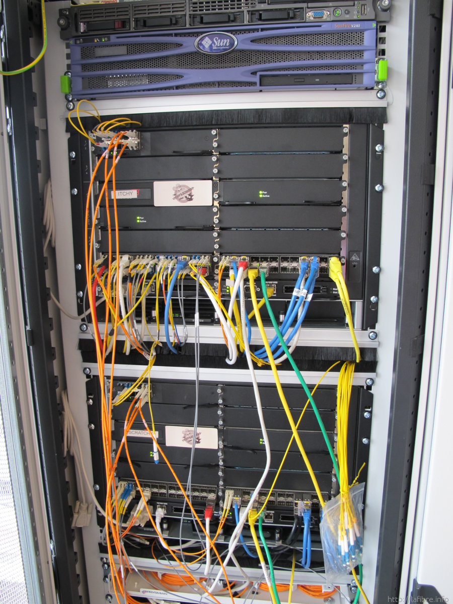
To build, maintain, and troubleshoot enterprise environments, we must understand the anatomy of building infrastructure, the geometry of equipment racks, the discipline of cable management, and the thermodynamics of hardware cooling.
If you view a multi-story enterprise building as a living organism, its networking infrastructure functions exactly like a central nervous system. Signals must travel from the outermost extremities (a workstation on the 10th floor) back to a central brain, and from there, out to the rest of the world. We structure this using distinct physical locations.
The Main Distribution Frame (MDF)
A Main Distribution Frame is the primary central interconnect point for a building network. Think of this as the core of the building's digital nervous system. It bears two massive responsibilities:
- The Main Distribution Frame routes traffic to internal enterprise networks, distributing data out to the rest of the facility.
- The Main Distribution Frame serves as the connection point to external telecommunication service providers.
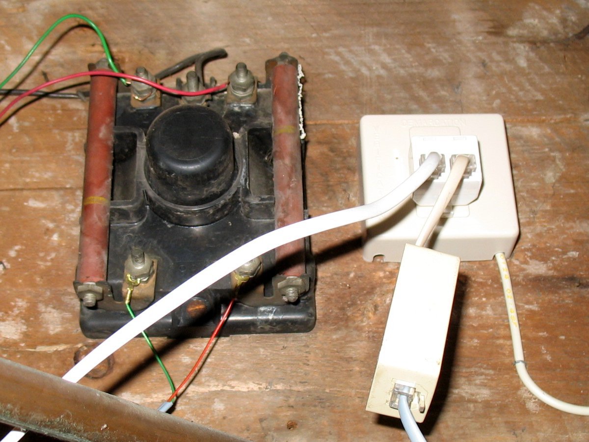
Because the MDF interfaces with the outside world, the external service provider connection enters a building at the demarcation point. The demarcation point is typically located within the Main Distribution Frame. This point is crucial for troubleshooting and legal liability: it is the precise physical boundary where the service provider's responsibility ends and your enterprise's responsibility begins. If a line is cut outside the demarcation point, you call the ISP; if it is cut inside, you pull out your own tools.
The Intermediate Distribution Frame (IDF)
Because a single central room cannot practically run individual copper cables to every single desk across a sprawling campus or a skyscraper (copper cables have severe distance limitations), we build regional hubs. An Intermediate Distribution Frame provides a local connection point for end-user devices on a specific floor.
An Intermediate Distribution Frame connects local floor workstations to the Main Distribution Frame. You will find at least one IDF per floor, acting as an aggregation point.
The Cabling Hierarchy
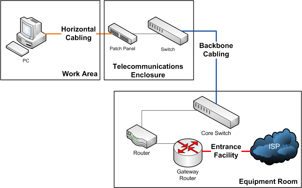
- Horizontal cabling links end-user workstation wall jacks to an Intermediate Distribution Frame. It is called "horizontal" because it physically runs horizontally through the ceilings and walls of that specific floor.
- Vertical cross-connect cabling links an Intermediate Distribution Frame to the Main Distribution Frame. Because it forms the central spine of the building's network, vertical cross-connect cabling is also known as backbone cabling.
Step inside an MDF or an IDF, and you will immediately see rows of standardized metal frames holding the equipment. The physical dimensions of this industry have been standardized to ensure any vendor's switch can fit into any facility's rack.
The standard width for mounting equipment in a network rack is 19 inches.
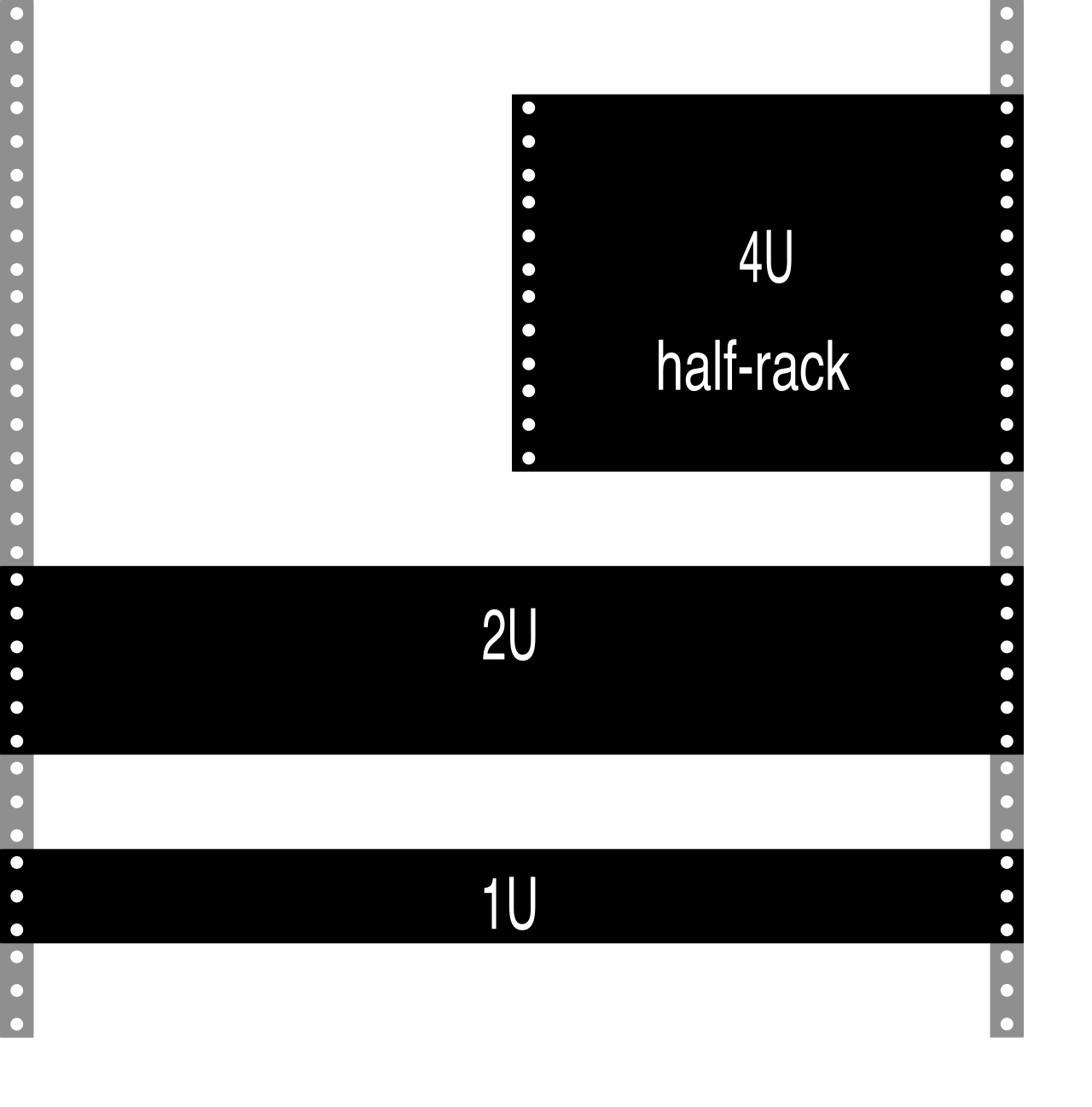
Vertical space, however, is the real estate of the datacenter. Network rack vertical height is measured using a standard unit called a Rack Unit. A Rack Unit is abbreviated as U or RU. One standard Rack Unit equals exactly 1.75 inches in height. Network equipment is sized in multiples of this unit: a standard patch panel might be 1U, a switch might be 2U, and a heavy-duty chassis router might be 10U.
A standard full-size network equipment rack is typically 42U in height, providing roughly six feet of vertical mounting space.
When selecting these racks, engineers must choose between structural designs based on the physical weight of the hardware:
- Two-post network racks primarily support lightweight networking equipment, such as patch panels and standard 1U edge switches. They bolt to the floor but only support equipment from the front mounting ears.
- Four-post network racks provide physical structural support for heavy networking equipment. When deploying massive core switches, dense blade servers, or heavy Uninterruptible Power Supplies (UPS), a four-post rack is mandatory to distribute the weight and provide front and rear stabilization.
Organizing the Chaos: Panels and Terminations
You never plug a cable directly from a wall or ceiling run straight into a network switch. Instead, building cables are permanently punched down into panels, and short "patch cables" bridge the gap to the switch.
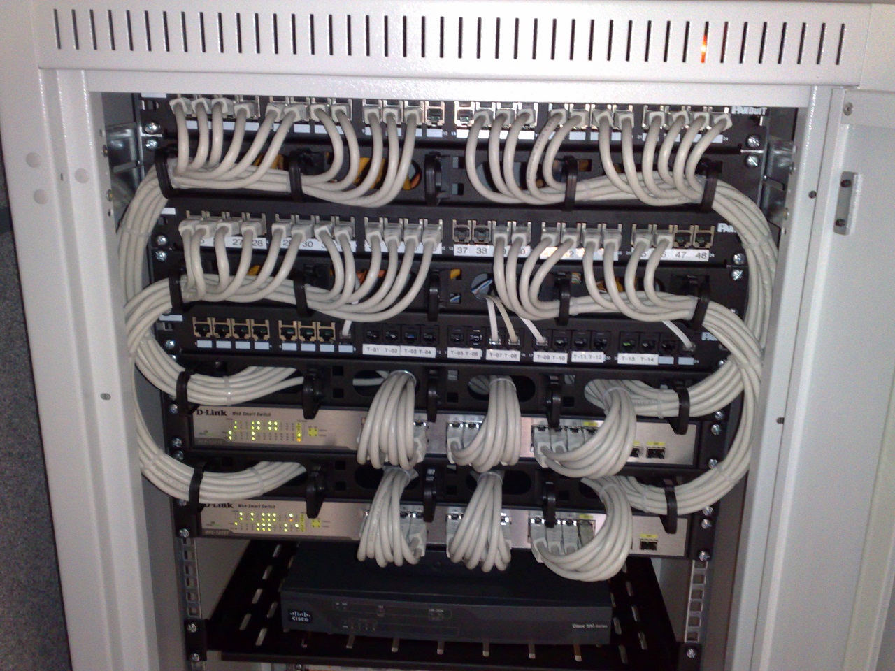
A patch panel is a passive hardware device featuring multiple ports to organize cable runs. Beyond organization, patch panels serve a vital protective function: patch panels protect network switch ports from physical wear during frequent cable moves. If an end-user needs to be moved to a different VLAN, you unplug the $3 patch cable, not the permanent building cable. If the connector degrades from hundreds of insertions, replacing a cheap patch cable is trivial; replacing a damaged port on a $10,000 enterprise switch is a disaster.
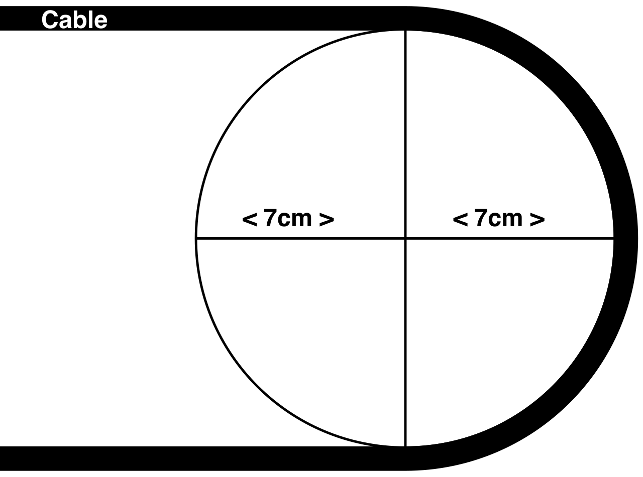
For fiber optics, the principles of protection are even stricter. A fiber distribution panel provides a termination point for incoming fiber optic cables. Because glass is incredibly fragile, fiber distribution panels use specialized splice trays to protect delicate fiber optic strands from physical damage. These trays securely loop the excess glass strands at specific bend radiuses, ensuring the light signal does not refract or break due to physical stress.
Information security professionals often joke that if a threat actor can physically touch your server, it is no longer your server. Because the MDF is the central nervous system, Main Distribution Frame rooms require physical access control mechanisms to prevent unauthorized network tampering.
Security operates in concentric rings:
- Room-Level Security:
- Smart badge readers restrict physical access to network equipment rooms using radio frequency identification (RFID) cards. This creates a digital audit trail of exactly who entered the room and when.
- For highly sensitive environments, biometric access controls use physical human characteristics—such as fingerprint scanners or retinal readers—to authenticate personnel entering an equipment room. Badges can be stolen; fingerprints cannot.
- Rack-Level Security: Once inside the room, individual hardware still requires protection. Server rack doors utilize physical locks or combination keypads to restrict physical access to networking hardware. This ensures that even if a vendor or technician is allowed in the room, they can only touch the specific rack they are authorized to service.
- Public Space Security: Sometimes an IDF simply will not fit in a dedicated closet, and edge equipment must be placed in a warehouse, a classroom, or a hallway. In these scenarios, locking cabinets enclose network equipment in public spaces to prevent unauthorized physical access.
Networking equipment consumes massive amounts of electricity, and the byproduct of that electrical consumption is heat. If you pack forty switches into a steel cabinet, they will rapidly cook themselves. Therefore, network equipment layouts must manage airflow to prevent hardware overheating.
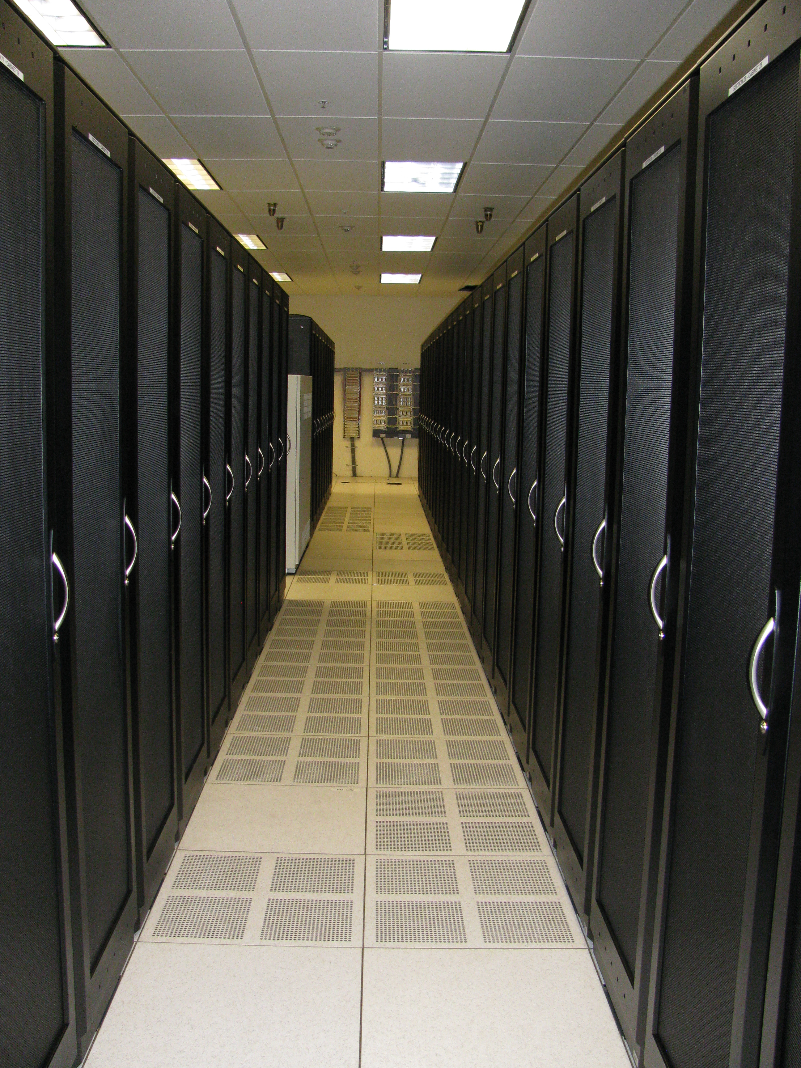
In a modern datacenter, we do not simply blast cold air into a room; we engineer a deliberate thermodynamic river. This is achieved through the hot aisle and cold aisle layout, which physically separates cold intake air from heated exhaust air in a server room.
- In a cold aisle configuration, the front intake sides of equipment racks face each other across a shared walkway. We pump chilled air exclusively into this aisle.
- In a hot aisle configuration, the rear exhaust sides of equipment racks face each other to collect warm air, which is then pulled up into return vents and sent back to the air conditioning units.
To deliver this cold air effectively, modern facilities utilize specific architecture. Raised floors in server rooms create an empty space underneath the equipment racks. The space underneath raised server room floors acts as a plenum to distribute pressurized cold air to equipment racks. Perforated floor tiles in the cold aisle allow this pressurized cold air to escape upward, directly in front of the equipment intakes.
Aligning the Equipment
Airflow is not magic; fans mechanically pull air from one side of a switch to the other. Network switch airflow direction must align with the specific hot and cold aisles of the rack placement. If you mount a switch backward, it will pull hot exhaust air into its chassis and quickly fail.
Network equipment airflow direction is often categorized as front-to-back or back-to-front. Because network switches require cables (which typically face outward toward the technician), we also describe airflow in relation to the ports:
| Airflow Direction | Port-side Description | Mechanism |
|---|---|---|
| Front-to-back airflow | Port-side intake switches | Pulls cool air into the front port side of a network switch. Expels heated air out the rear power supply side of a network switch. |
| Back-to-front airflow | Port-side exhaust switches | Pulls cool air into the rear power supply side of a network switch. Expels heated air out the front port side of a network switch. |
Why the distinction? Top-of-rack (ToR) switches in a server cabinet are often mounted at the back of the rack so their ports are close to the server network cards. In this setup, the "port side" of the switch is actually facing the hot aisle. To avoid pulling in hot air, engineers buy a port-side exhaust (back-to-front) switch, which pulls cold air from the front of the rack (the power supply side) and blows the heat out over the ports.
Sealing the System: Blanking Panels
The entire hot/cold aisle architecture relies on strict air pressure. If you have a 42U rack, but you only install 30U of equipment, you have 12U of empty space. Air is lazy; it follows the path of least resistance. Instead of pushing through the dense, restrictive fans of your routers, the cold air will just bypass the equipment by slipping through the empty rack space. Worse, hot exhaust air will be sucked back through those gaps into the cold aisle.
To fix this, blanking panels cover empty rack spaces. Think of them as sealing a leak in a dam. By installing these simple metal or plastic plates, blanking panels prevent hot exhaust air from circulating back to the cold intake aisle, forcing the pressurized cold air to travel exactly where it is needed: directly through your costly networking hardware.