Power and Environmental Factors
Not sure you’re ready?
Take the ~3-minute readiness diagnostic and see where you stand.
Imagine a flawless network architecture—exquisitely routed protocols, meticulously tuned traffic shaping, and robust, impenetrable encryption. Now, unplug the power cord. In a fraction of a second, that mathematical perfection collapses into inert silicon and plastic. Network engineering is fundamentally tethered to the physical world: governed by electrons, heat, moisture, and chemical reactions. To build resilient infrastructure, we cannot stop at the OSI model; we must master the unseen electrical and environmental forces that dictate whether our devices function, degrade, or catch fire.
Electricity is the lifeblood of our infrastructure, but it is not a gentle, passive resource. We must define exactly what we are drawing from the wall and understand its limits.
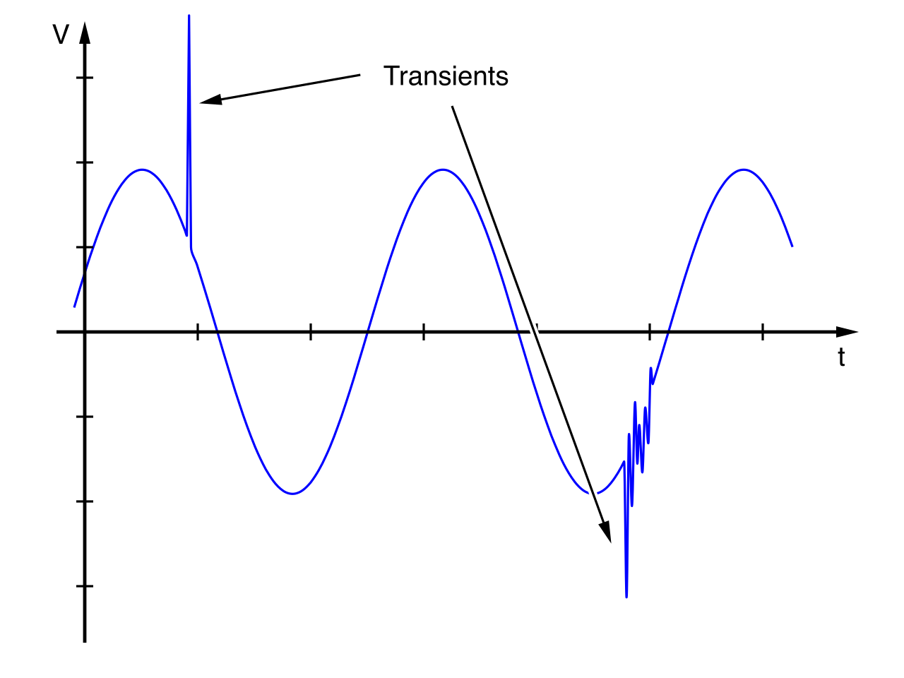
At the foundation is voltage, which represents the measure of electrical potential difference in a circuit. It is the "pressure" pushing electrons through our equipment. When this pressure is erratic, problems arise. Electrical voltage fluctuations such as sags (undervoltage) and surges (overvoltage) can cause hardware degradation in delicate network components over time.
To power a rack of equipment, we must calculate the power load, which refers to the total amount of electrical power consumed by all devices operating on a specific electrical circuit.
Power Load Calculation: To determine if a circuit can safely handle a rack of equipment, you must sum the maximum wattage or Volt-Amp (VA) ratings of all devices to ensure the circuit capacity is not exceeded.
You cannot simply load a circuit up to 100% of its mathematical limit. Electrical safety guidelines recommend that continuous network equipment power loads should not exceed 80 percent of a circuit breaker's maximum rated capacity. If you ignore this threshold and keep stacking switches in a rack, physics will force your hand: exceeding the maximum power load of an electrical circuit causes circuit breakers to trip. A tripped circuit breaker immediately disconnects electrical power to all attached network devices, instantly taking your network offline.
Once we have a safe power circuit, we need a way to hand that power to individual servers and switches. We use a Power Distribution Unit (PDU), a specialized electrical device designed to distribute electricity evenly to multiple networking devices within an equipment rack. Crucially, modern PDUs incorporate surge protection to shield network equipment from electrical anomalies such as voltage spikes.
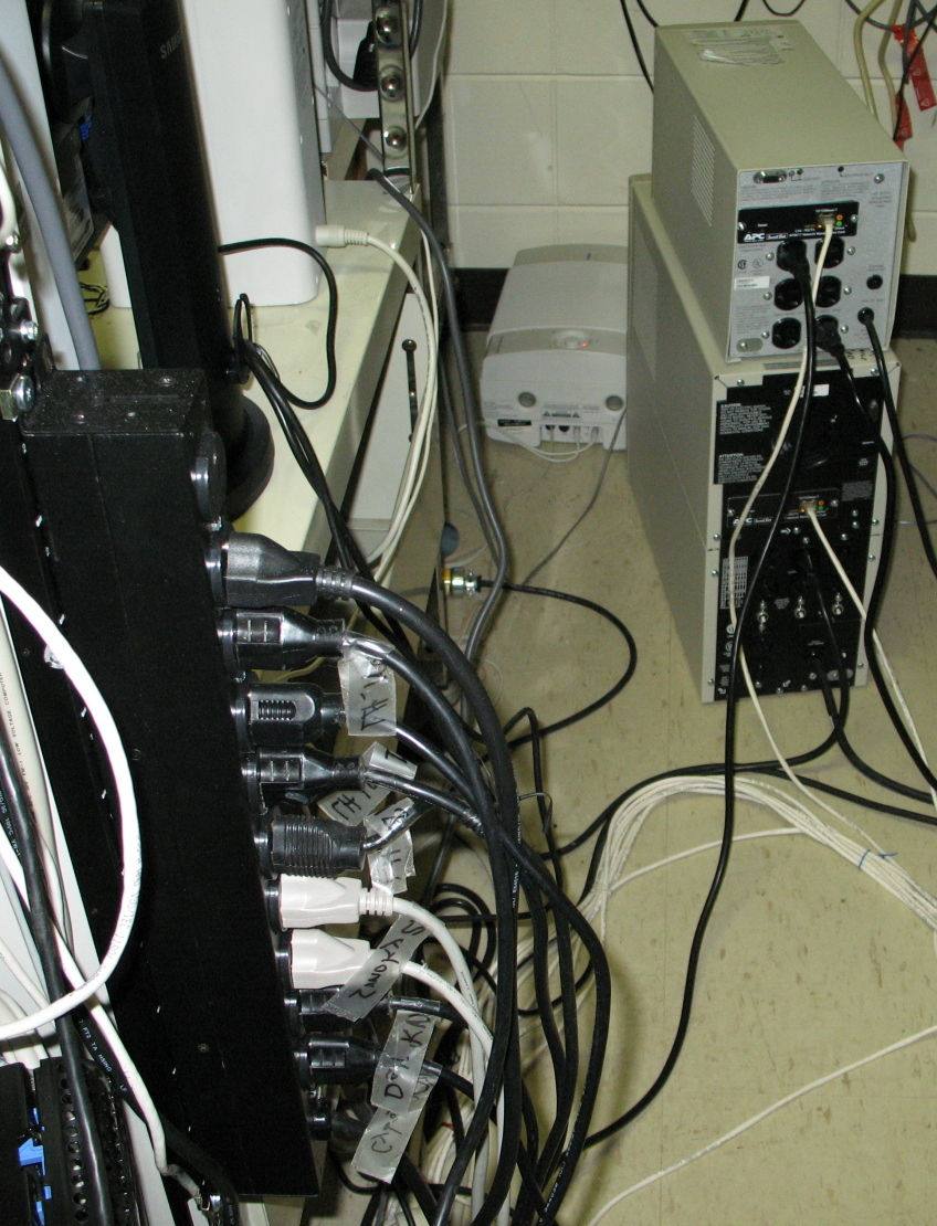
But power distribution has evolved into a smart science:
- Intelligent Power Distribution Units (iPDUs) allow remote monitoring of power consumption and voltage metrics over a network connection.
- Switched Power Distribution Units (PDUs) provide another layer of control, allowing network administrators to remotely power cycle individual electrical outlets—invaluable when a distant router locks up and needs a hard reboot.
Eliminating the Single Point of Failure
If an entire rack relies on a single PDU, a failure in that unit brings down the entire rack. To survive hardware failures, we rely on redundant power supplies built into our switches and routers. However, plugging two power supplies into the same PDU is a logical fallacy.
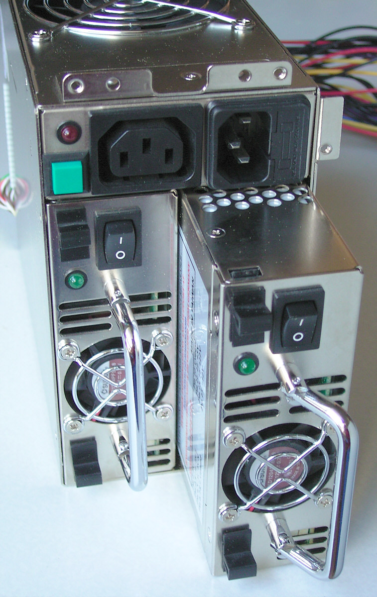
Dual-power networking devices should have each power supply connected to a completely separate Power Distribution Unit (PDU). Furthermore, these redundant power supplies within a single network device must connect to completely separate physical electrical circuits. Connecting redundant power supplies to separate electrical circuits effectively eliminates single points of electrical failure, from the device power supply all the way back to the breaker panel.
When utility power abruptly fails, networking equipment cannot simply halt. We need localized energy reserves. An Uninterruptible Power Supply (UPS) provides temporary battery power to network devices during a primary utility power failure.
UPS electrical capacity is typically measured in Volt-Amps (VA) or Watts. When sizing a unit, you cannot simply match the exact load. An Uninterruptible Power Supply should provide a power capacity 20 to 30 percent higher than the calculated power load of the connected devices.
The UPS serves two distinct strategic purposes depending on the facility:
- The Graceful Exit: In smaller environments, the UPS provides enough battery runtime to safely perform a graceful shutdown of network devices, preventing data corruption.
- The Bridge: In enterprise data centers, the UPS provides enough battery runtime to bridge the power gap until a backup generator starts.
UPS Topologies
Not all UPS systems operate the same way. We classify them by how they handle the handoff from utility to battery:
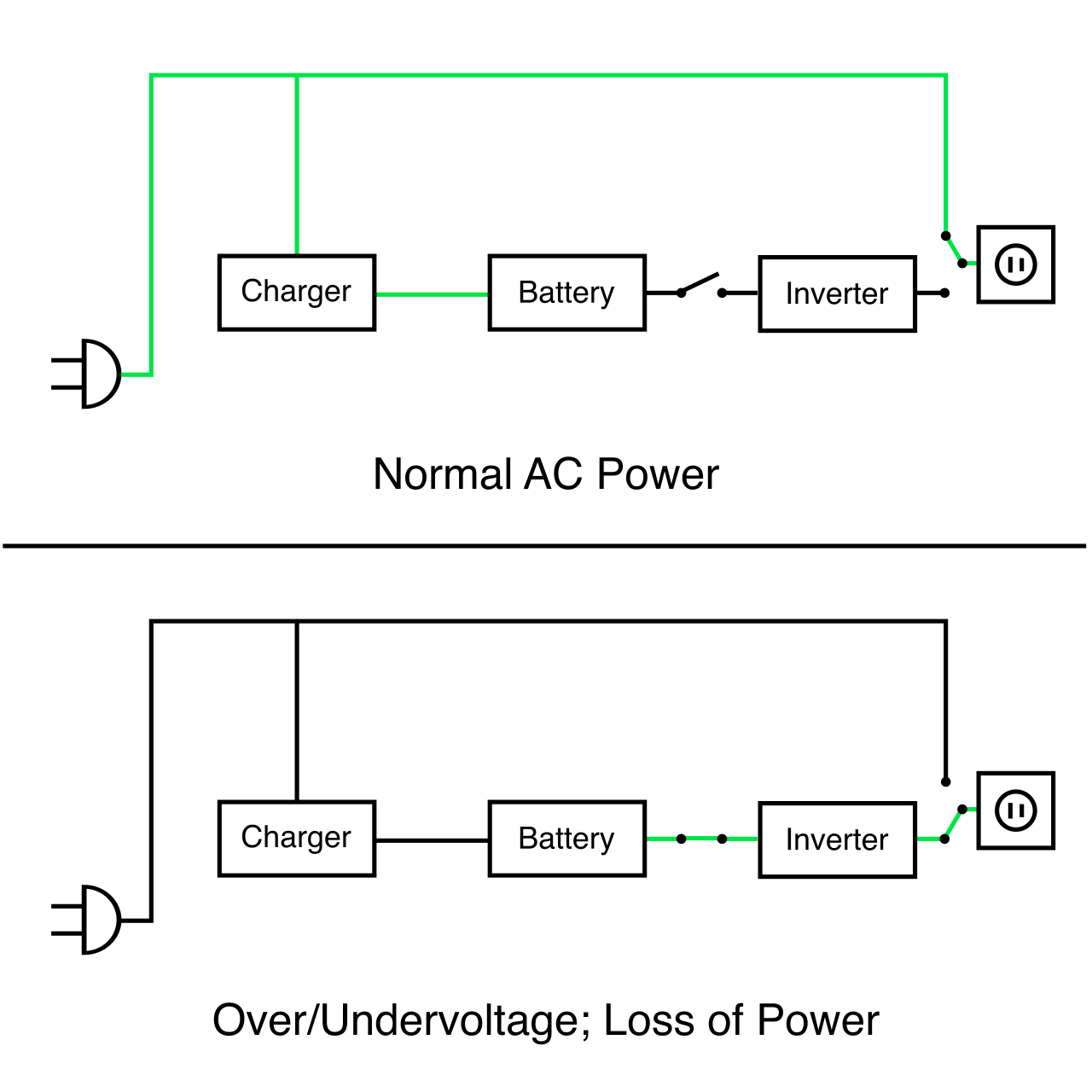
- Offline UPS: Switches network equipment to battery power only when a utility voltage drop is detected. There is a microscopic transfer time.
- Line-interactive UPS: Uses an internal autotransformer to correct minor voltage fluctuations (sags and swells) without actually switching to battery power, saving battery lifespan.
- Online UPS: This is the gold standard for sensitive equipment. It continuously supplies power from the battery while the battery is simultaneously charged by the main utility. Because the equipment is always running off the battery inverter, there is zero transfer time during a blackout.
Sustained Outages
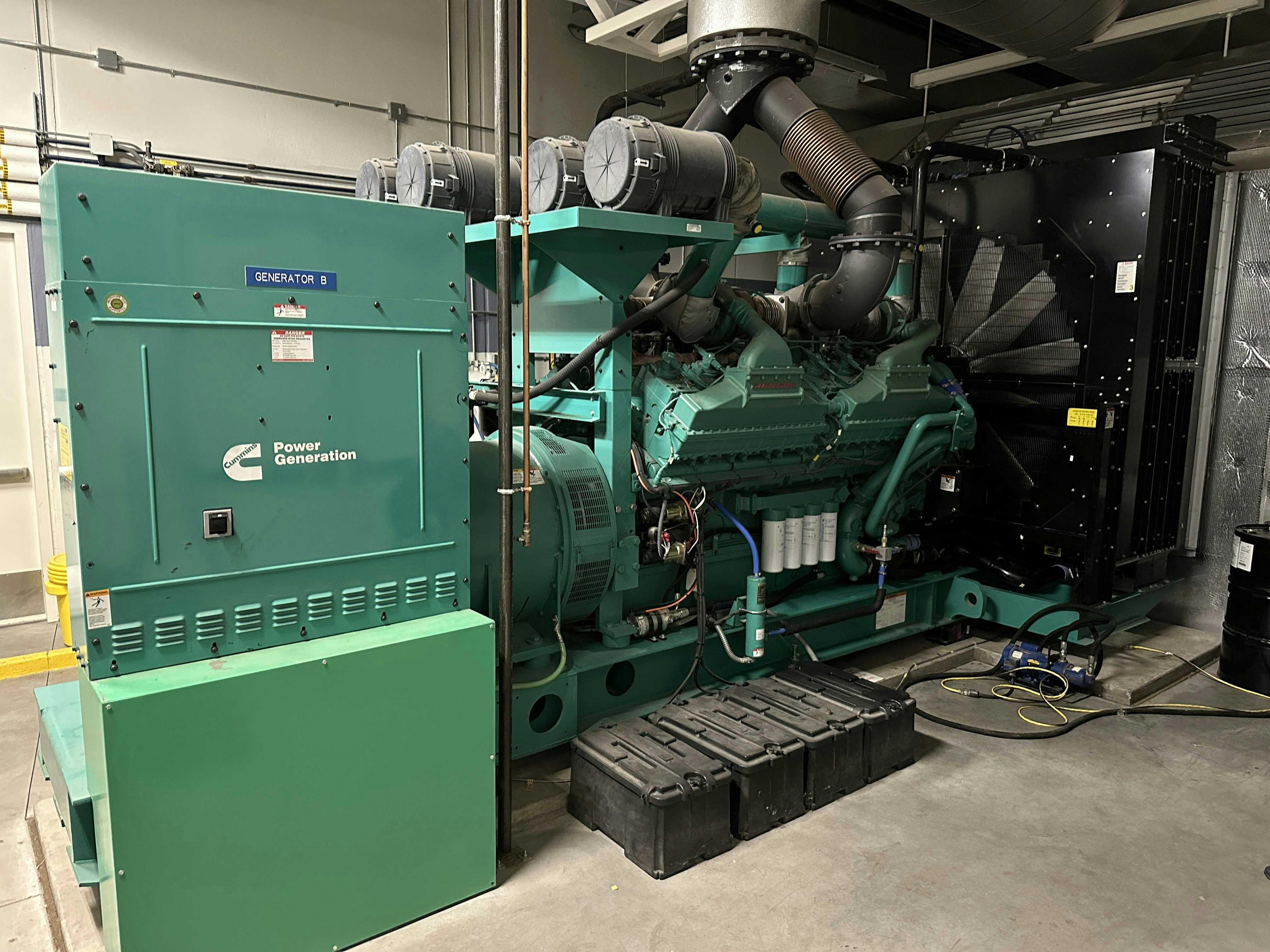
A UPS battery will eventually drain. For extended utility outages, backup generators provide long-term electrical power for network facilities. These massive engines for data centers are typically powered by diesel, natural gas, or propane fuels. To make the transition seamless, an Automatic Transfer Switch (ATS) automatically shifts the facility power source from the utility grid to a backup generator during an outage.
Before we explore the atmospheric conditions of the data center, we must define how our gear is physically mounted.
- Two-post equipment racks are typically used for lightweight networking equipment such as edge switches and patch panels.
- Four-post equipment racks provide the necessary structural support for heavy networking equipment such as large physical servers and core routers.
Computing is ultimately the process of turning electricity into heat. If we do not relentlessly remove that heat, the physics of our silicon will turn against us. Heating, Ventilation, and Air Conditioning (HVAC) systems regulate the ambient temperature within a data center, manage the cooling airflow routing, and regulate the ambient humidity.
If HVAC systems fail, the consequences are immediate:
- High Temperatures: Excessively high ambient temperatures can cause network equipment to experience thermal throttling or permanent hardware failure. Before hardware physically melts, excessively high ambient temperatures can cause network equipment to experience random operating system reboots.
- Low Temperatures: Conversely, over-cooling is dangerous. Extremely low ambient temperatures can cause network equipment malfunctions such as severely slowed response times.
Airflow Architecture
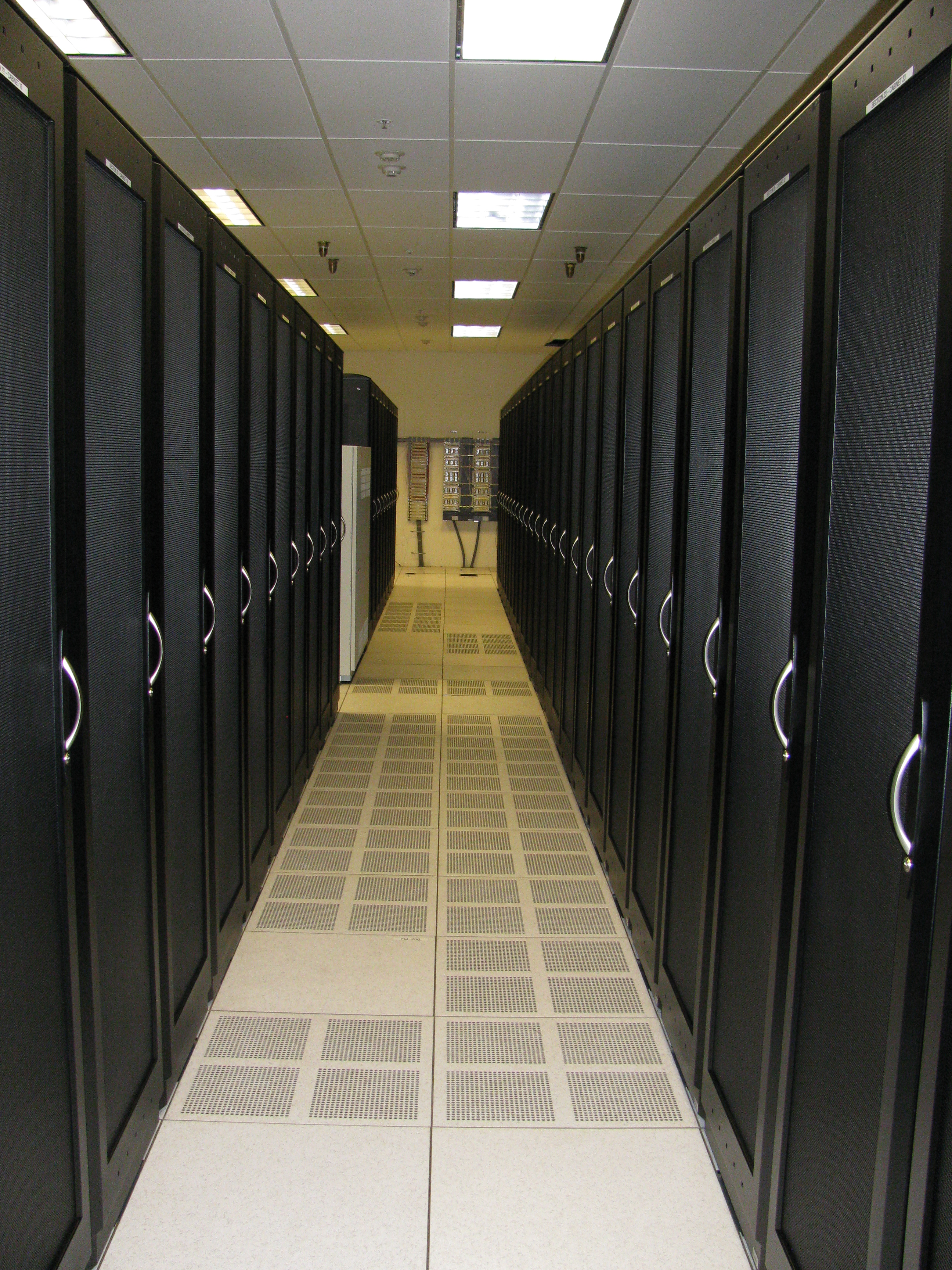
To optimize cooling, we do not just pump cold air randomly into a room. We use hot aisle and cold aisle containment, a physical layout design that aligns server racks to optimize data center cooling efficiency.
- A cold aisle design ensures that chilled HVAC air is delivered directly to the intake side of the networking equipment racks.
- A hot aisle design collects the heated exhaust air from equipment racks and directs the exhaust back into the HVAC return system.
To assist in this airflow, raised floors in a data center provide a physical space below the equipment racks to distribute cold HVAC air outward from the cooling units directly to the cold aisles.
Managing The Air Inside the Rack
You must meticulously control how air moves through the rack. Blanking panels are physical plates installed in empty rack spaces to prevent hot exhaust air from mixing with cool intake air. If you leave gaps in your rack, hot air recirculates right back into the server intakes.
Furthermore, switches are manufactured with specific airflow directions:
- A port-side intake switch configuration pulls cooling air through the front panel network ports and exhausts heated air out the rear power supply side.
- A port-side exhaust switch configuration pulls cooling air through the rear power supply side and exhausts heated air out the front panel network ports.
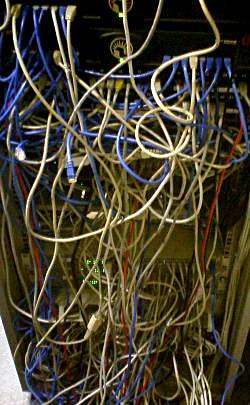
Airflow can also be killed by a lack of discipline. Poor physical cable management within a rack can physically obstruct device cooling airflow. This obstructed cooling airflow from poor cable management can cause localized network equipment overheating, creating "hot spots" even in a perfectly chilled room. To prevent this, we use cable trays—elevated physical structures used to route network cables neatly without obstructing under-floor cooling airflow.
Humidity is the measure of airborne moisture or water vapor present in a given environment. It is the silent killer of network infrastructure.
We must thread a needle between two extremes:
- Excessively low humidity increases the risk of electrostatic discharge (ESD) damaging sensitive network hardware. Dry air is a perfect conductor for static shocks.
- Excessively high humidity promotes condensation and metallic corrosion on internal network device components.
Therefore, maintaining strict humidity levels in a data center prevents harmful static electricity discharges while simultaneously preventing network equipment metallic corrosion. The recommended relative humidity level for a network equipment environment is typically maintained between 40 percent and 60 percent.
Note: You do not need to walk the aisles with a thermometer. Intelligent Power Distribution Units (iPDUs) often integrate environmental monitoring sensors to track both rack-level temperature metrics and rack-level humidity metrics centrally.
When electricity and heat escape our control, fire is the result. Fire suppression systems detect and extinguish fires using specific chemical agents, water, or inert gases.
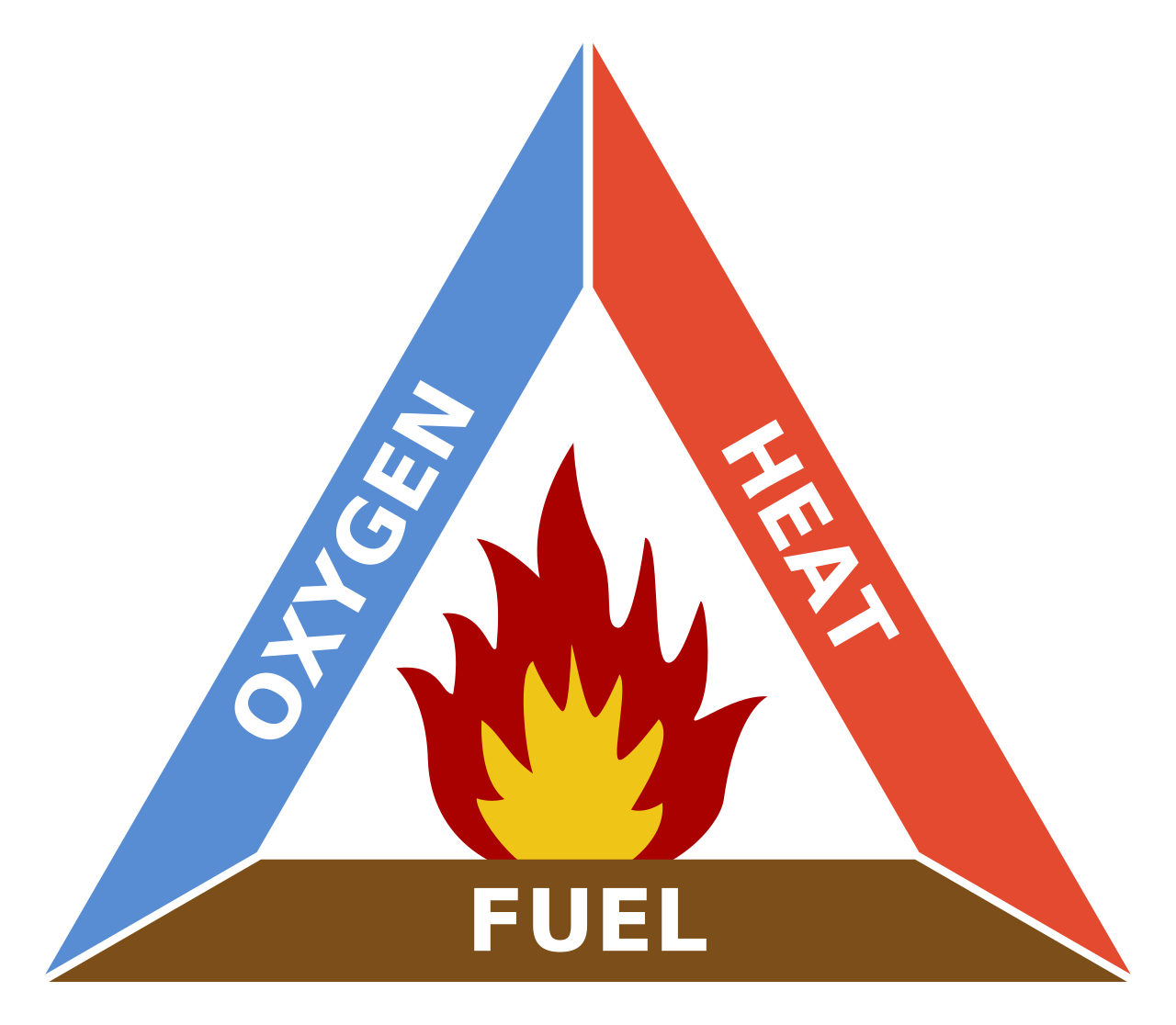
To defeat a fire, we look to the fire triangle—a conceptual model illustrating that heat, fuel, and oxygen must all be present for a fire to burn. The physics are simple: removing any single element of the fire triangle will successfully suppress or extinguish an active fire.
Suppression Methods
Because water and electricity are a disastrous combination, water-based fire sprinkler systems are rarely used in primary server rooms due to the high risk of catastrophic electrical shorts. If building codes mandate water, facilities use pre-action sprinkler systems. These systems hold water outside the data center piping until a secondary fire sensor activates, which significantly reduces the risk of accidental water discharge onto expensive networking equipment.
Ideally, we use gas-based solutions that leave our hardware intact:
- Clean agent fire suppression systems discharge gaseous chemicals to extinguish fires without leaving a conductive residue. A prime example is the FM-200 fire suppression agent. It operates twofold: it removes heat energy from a fire, and it chemically interrupts the combustion reaction of a fire.
- Inert gas fire suppression systems take a different path. They deploy argon or nitrogen to lower the ambient oxygen concentration below the threshold required for combustion, literally starving the fire of oxygen.
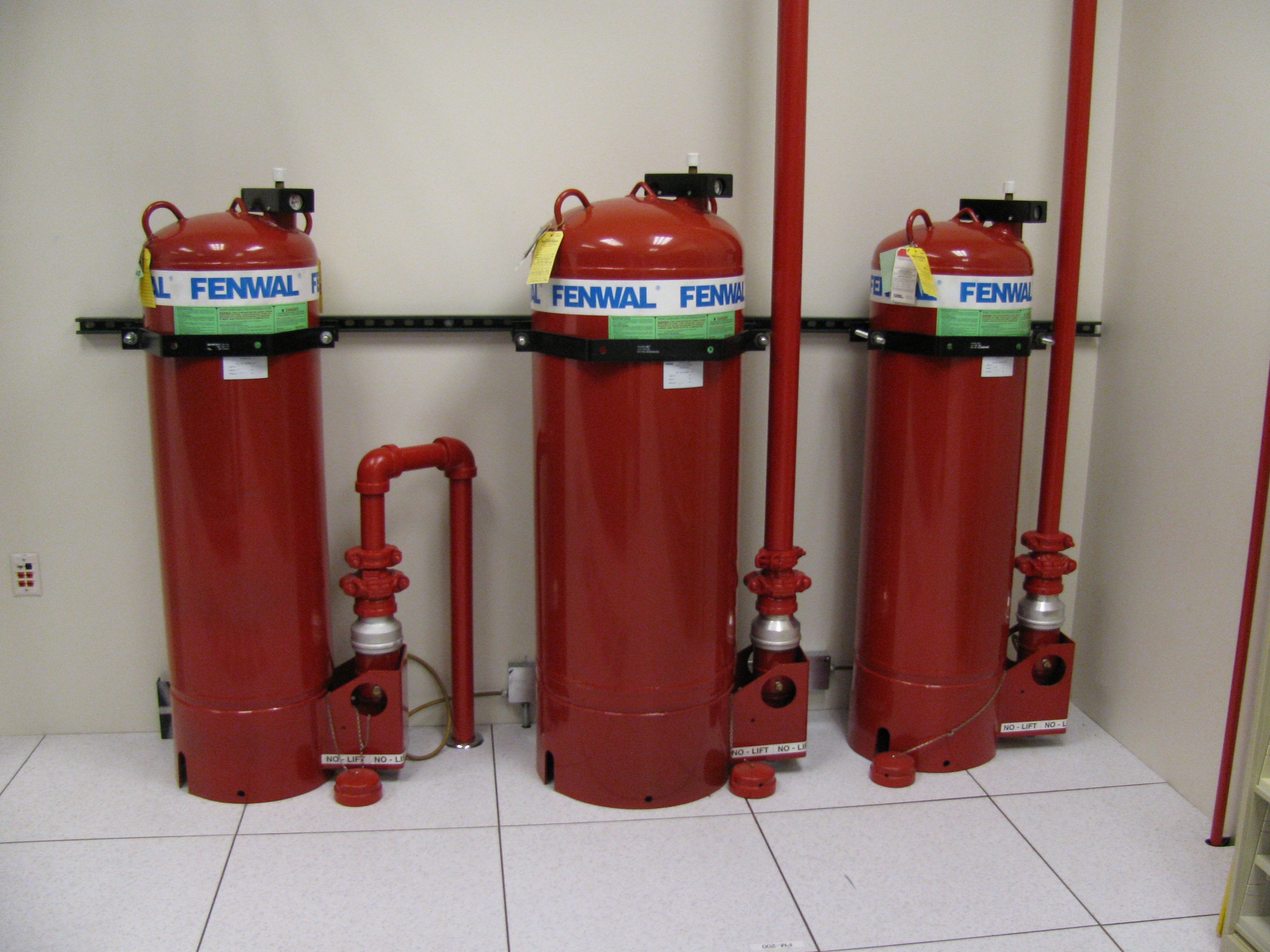
For localized incidents, you must be prepared manually. However, standard extinguishers will conduct electricity right back into your body. Handheld fire extinguishers designated for network equipment spaces must be explicitly rated for Class C electrical fires.
By combining rigorous electrical capacity planning, strategic redundancy, precise thermodynamic controls, and specialized fire suppression, we build environments where our network infrastructure can operate safely, predictably, and flawlessly.