Hardware and Transceiver Troubleshooting
Not sure you’re ready?
Take the ~3-minute readiness diagnostic and see where you stand.
Beneath the high-level abstractions of routing protocols and cloud applications lies a physical reality governed strictly by the laws of electricity and optics. A network is ultimately a machine that moves electrons and photons through copper and glass. When a pan-tilt-zoom security camera fails to power on, or a multi-gigabit fiber backbone suddenly drops packets, the failure is rarely a mystery of software; it is a failure of physics. To resolve hardware-centric network outages, an engineer must understand exactly how direct current traverses an Ethernet cable and how pulses of light propagate through a microscopic glass core. Diagnosing these physical layer faults—specifically power delivery limitations and transceiver mismatches—requires moving beyond configuration screens and interrogating the physical link itself.
We often think of Ethernet purely as a data conduit, but it is also a highly capable power grid. The concept is elegant: inject direct current (DC) over the unused or center-tapped pairs of a twisted-pair cable, allowing a single cable to provide both data and power to edge devices like access points, IP phones, and cameras.
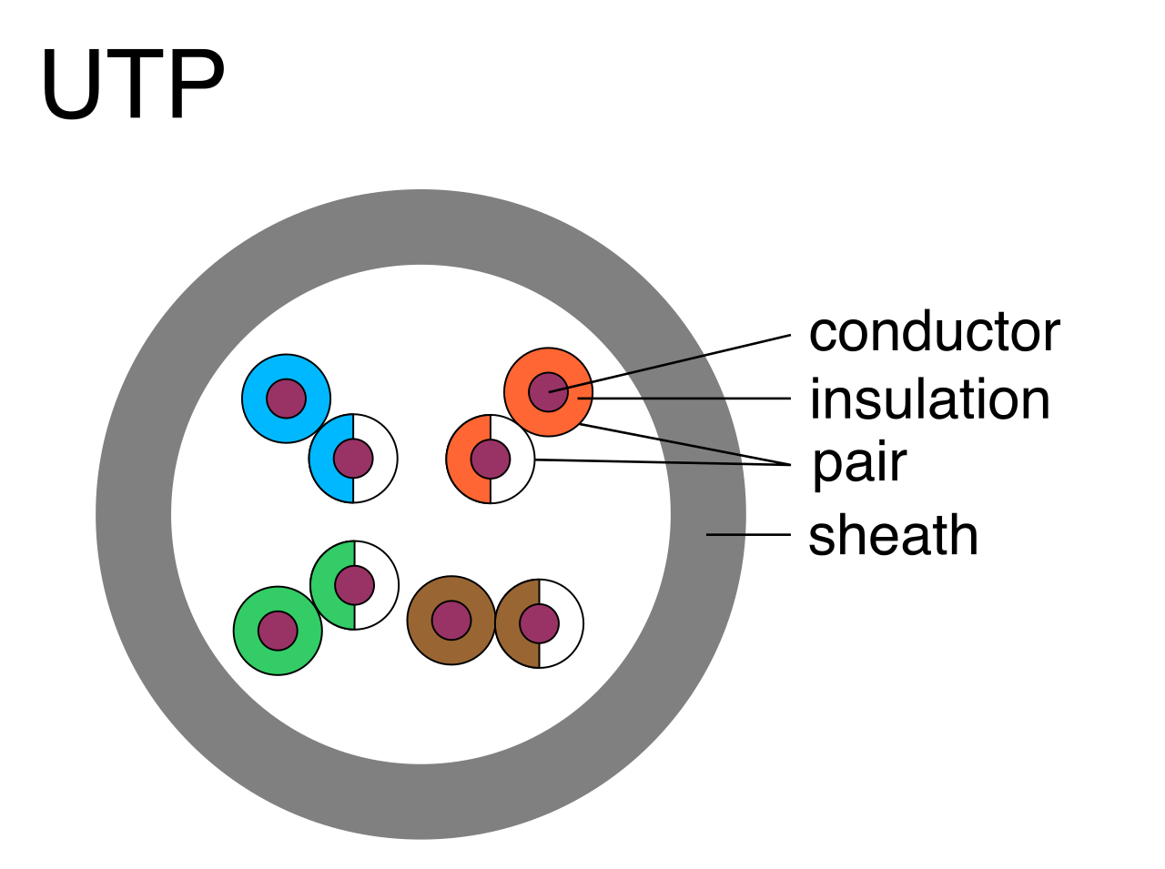
However, electricity follows strict rules. You cannot draw more power than the source can provide, and pushing power over long distances incurs penalties.
The PoE Standards and Switch Power Budgets
Power over Ethernet is not a monolithic technology; it is a tiered system of IEEE standards engineered to support increasingly demanding devices.
| Standard Name | Common Name | Max DC Power Provided (at Switch Port) |
|---|---|---|
| IEEE 802.3af | Power over Ethernet (PoE) | Up to 15.4 watts of DC power |
| IEEE 802.3at | Power over Ethernet Plus (PoE+) | Up to 30 watts of DC power |
| IEEE 802.3bt Type 3 | Power over Ethernet Plus Plus (PoE++) | Up to 60 watts of DC power |
| IEEE 802.3bt Type 4 | Power over Ethernet Plus Plus (PoE++) | Up to 100 watts of DC power |
When you plug a PoE-capable device into a switch, the switch does not simply blindly push power down the wire. A network switch has a maximum total Power over Ethernet power budget. Think of this like the main breaker panel in a house; while you might have forty 15-amp circuits, the main breaker might only support 200 amps total.
If you connect thirty cameras requiring 15 watts each, you need a 450-watt power budget. A switch denies power to a newly connected Power over Ethernet device if the remaining power budget is insufficient. The port will pass data, but the device will remain lifeless.

Diagnosing PoE Mismatches and Cable Drops
What happens when there is a fundamental disagreement between the power source and the device? Connecting a device requiring a higher Power over Ethernet standard to a switch supporting a lower standard prevents the device from powering on. In more insidious cases, the device might draw enough initial trickle power to boot its basic circuitry, but the moment it attempts to initialize a high-draw component—like a camera's motorized pan/tilt mechanism or infrared array—the voltage sags. This dynamic means connecting a device requiring a higher Power over Ethernet standard to a switch supporting a lower standard can cause the device to repeatedly reboot.
To verify what the switch is actually outputting, technicians use specialized diagnostic tools. A Power over Ethernet tester verifies the specific power standard provided by a switch port, taking the guesswork out of whether the switch or the endpoint is at fault.
If the switch lacks PoE capabilities entirely, or if its power budget is exhausted, you do not necessarily need to replace the switch. A Power over Ethernet injector is a hardware device used to add DC power to a standard network link, acting as an intermediary power supply.
Furthermore, power delivery is a negotiation. While hardware classification occurs instantly, network administrators use Link Layer Discovery Protocol (LLDP) to negotiate precise Power over Ethernet power requirements between a switch and a connected device. This allows a switch to allocate, for example, exactly 18 watts to a device rather than reserving a full 30-watt block, efficiently maximizing the switch's total power budget.
The Physics of the Wire: Copper is an imperfect conductor. Cable resistance causes a voltage drop over long Ethernet cable runs. The further the electricity travels, the more energy is lost as heat. Consequently, voltage drop can cause Power over Ethernet devices near the 100-meter distance limit to malfunction, even if the switch port is supplying the correct wattage.
When data throughput requirements exceed the physical limits of copper, we turn to light. Transceivers convert electrical signals from the switch's backplane into optical pulses, and vice versa.
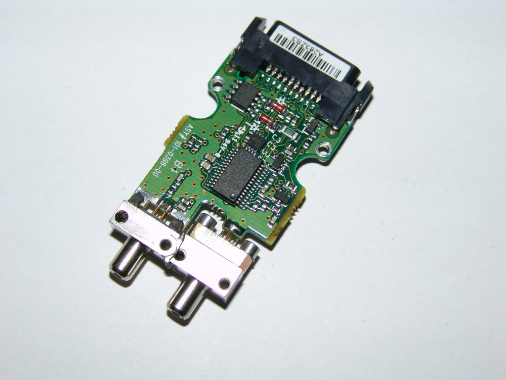
In modern networking, form factors dictate capacity:
- Small Form-factor Pluggable (SFP) transceivers support up to 1 Gigabit per second data rates.
- Enhanced Small Form-factor Pluggable (SFP+) transceivers support up to 10 Gigabits per second data rates.
The Mechanics of a Mismatch
Fiber optic communication relies on absolute symmetry. Both ends of the link must speak the exact same language of light. A transceiver mismatch occurs when the transceivers on opposite ends of a fiber link operate at different speeds (e.g., placing a 1 Gbps SFP on one side and a 10 Gbps SFP+ on the other without auto-negotiation compatibility).
Equally critical is the color of the light. A transceiver mismatch occurs when the transceivers on opposite ends of a fiber link operate at different wavelengths.
Fiber optics utilize specific infrared wavelengths optimized for either short-range or long-range transmission:
- Common multimode fiber transceivers operate at an 850 nanometer wavelength, using a wider glass core that allows multiple modes (paths) of light to bounce down the cable.
- Common single-mode fiber transceivers operate at a 1310 nanometer or 1550 nanometer wavelength, firing a highly focused laser straight down an incredibly narrow core for long distances.
Mixing these physical realities yields immediate failures. Connecting a single-mode fiber transceiver to a multimode fiber transceiver prevents the establishment of a network link entirely, as the differing wavelengths and tolerances cannot synchronize.
Even worse is mixing the cable media with the wrong optics. Connecting a single-mode fiber cable to a multimode transceiver causes severe optical signal dispersion. The narrow core of the single-mode cable effectively chokes the wide-angle light emission from the multimode transceiver, destroying the signal's integrity before it travels more than a few feet.
How do we troubleshoot something we cannot see? We ask the transceiver to report on its own physical state.
Digital Optical Monitoring (DOM) is a diagnostic standard for optical transceivers. Rather than guessing if a link is healthy, network administrators use Digital Optical Monitoring to view real-time optical signal strength metrics directly from the switch's command-line interface.
To understand these metrics, we must understand the unit of measurement. Optical signal strength is measured in decibels relative to one milliwatt (dBm). Because this is a logarithmic scale, a value of 0 dBm equals exactly 1 milliwatt of power. Negative values (e.g., -5 dBm, -12 dBm) represent fractions of a milliwatt, which is the standard operational range for most receivers.
When examining DOM output, you will see two primary metrics:
- Transmit (Tx) power measures the optical signal strength leaving a transceiver.
- Receive (Rx) power measures the optical signal strength arriving at a transceiver.
Troubleshooting optical links often comes down to verifying the Receive power against the manufacturer's strict tolerances:
- A Receive power level falling below the transceiver minimum receiver sensitivity threshold causes a link failure. The light is simply too dim for the photodiode to distinguish the signal from background noise.
- A Receive power level exceeding the transceiver maximum receiver overload threshold causes optical component damage. This occurs when a powerful long-haul single-mode transceiver is used over a very short distance without an inline attenuator, effectively blinding and burning out the receiving optic.
Light does not travel through glass without loss. Attenuation is the reduction of optical signal strength over the length of a fiber optic cable.
While natural attenuation occurs due to the distance of the glass, the most common causes of extreme attenuation are human error and environmental factors:
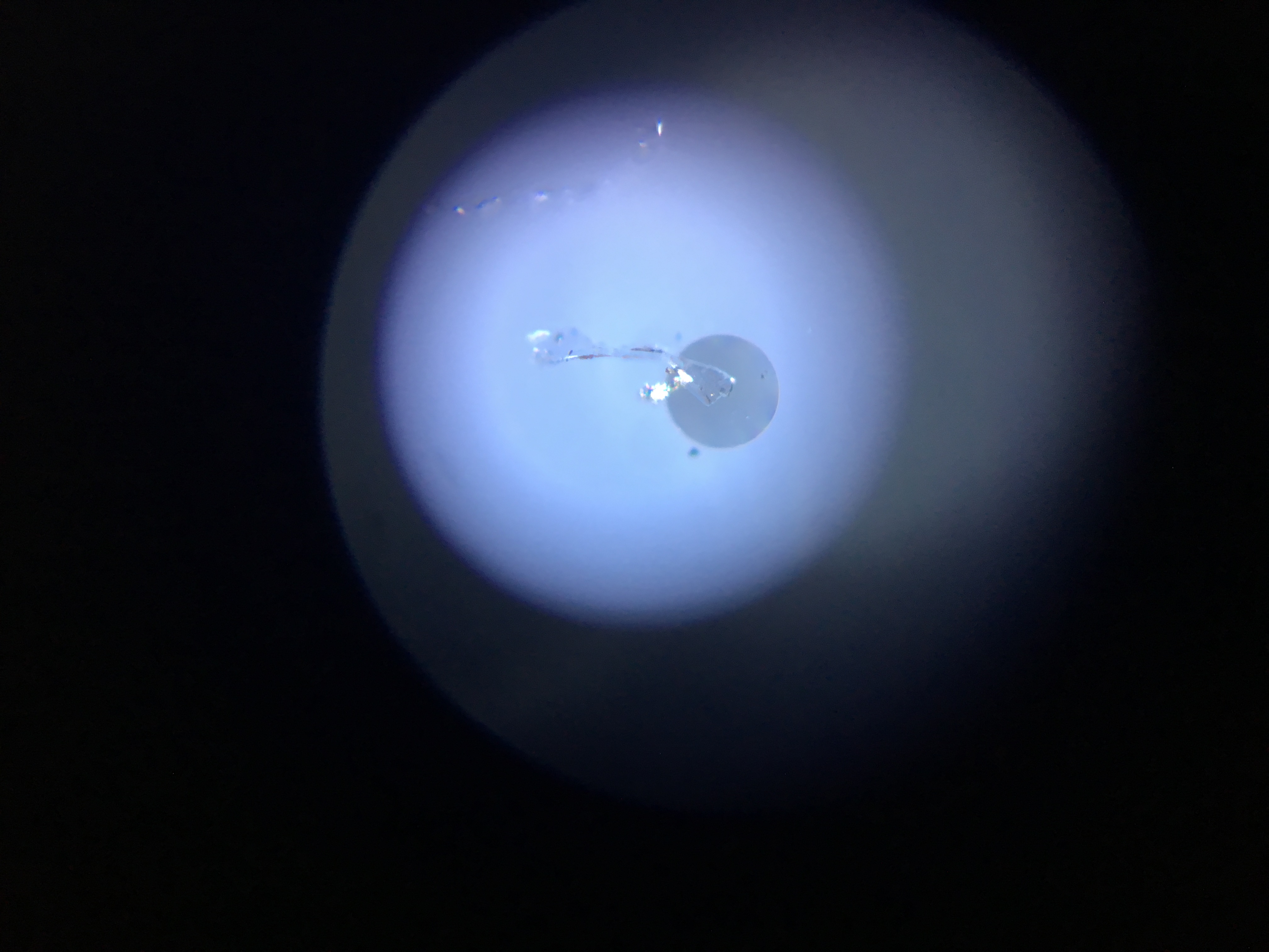
- Dust on fiber optic connectors attenuates the optical signal. A microscopic speck of dust on the ferrule of a fiber strand blocks light precisely where it needs to enter the transceiver. Consequently, dirty optical transceivers cause elevated bit error rates on a network link, as the degraded light causes the receiver to misinterpret 1s and 0s.
- Fiber optic cable macrobends attenuate the optical signal. If a fiber cable is bent too tightly around a rack post or tied too tightly with a zip-tie, the light exceeds the critical angle of reflection and escapes through the cladding of the cable, draining signal strength.
Finally, we arrive at the simplest, yet most frequent, cause of fiber optic outages: plugging the cables in backward.
Fiber optic communication requires the Transmit port on the local transceiver to connect to the Receive port on the remote transceiver. It is a loop; my mouth speaks to your ear, and your mouth speaks to my ear.
A transposed fiber connection occurs when the Transmit port of one device connects to the Transmit port of another device (Tx to Tx, and Rx to Rx). Because receivers are listening to silent receivers, and transmitters are firing into active transmitters, a transposed fiber connection prevents physical link establishment.
How do you find the reversed strand in a dark datacenter? You introduce visible light. Technicians use a visual fault locator (VFL) to identify which fiber strand is transmitting light.
Diagnostic Tool: A visual fault locator emits a visible red laser into a fiber optic cable. By shining this bright red light into one end of a strand, the technician at the remote patch panel can instantly see which strand glows red, confirming continuity and orientation.
Once the transposed strand is identified, it must be corrected. Fiber patch cables commonly use duplex connectors, which bind the two strands together in a single plastic housing. Fortunately, Duplex Local Connector (LC) clips allow technicians to swap the individual fiber strands to fix a transposed transmit and receive issue. You simply unclip the plastic retaining bracket, slide the two LC connectors out, reverse their positions, and snap them back into the clip.
By mastering the precise power budgets of PoE and the fragile, exacting physics of optical transceivers, a network engineer moves from guessing at configuration issues to definitively proving the integrity of the physical layer.