Troubleshooting Network Services
Not sure you’re ready?
Take the ~3-minute readiness diagnostic and see where you stand.
A digital network is an exquisite engine of distributed decision-making. At every microsecond, thousands of disparate devices—switches, routers, and endpoints—must collectively agree on the precise geometry of their environment. When this consensus is perfectly calibrated, data flows effortlessly. However, when configuration errors introduce contradictions into this underlying logic, the entire system can violently collapse. The study of network troubleshooting is not simply memorizing commands; it is the study of how interconnected systems handle paradoxes, loops, and exhaustion. To validate your skills as a network technician, you must understand how to diagnose these structural failures at their root.
At the Data Link layer (Layer 2), switches are fiercely efficient, but they are inherently trusting. They forward broadcast traffic out of every port to ensure it reaches its destination. If you introduce a redundant physical link without a control mechanism, you create an infinite acoustic feedback loop. A Layer 2 network loop can cause a broadcast storm that rapidly overwhelms available network bandwidth, rendering the entire local area network completely unusable in seconds.
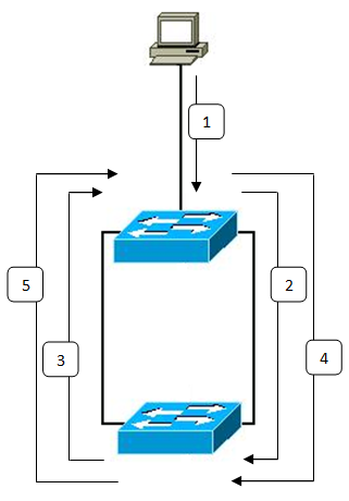
To safely permit redundant physical cabling—which we need for hardware resilience—we must logically sever the loops. This is the domain of the Spanning Tree Protocol. Spanning Tree Protocol (STP) prevents Layer 2 switching loops by blocking redundant network paths. It effectively turns a web of connections into a strict, loop-free tree structure.
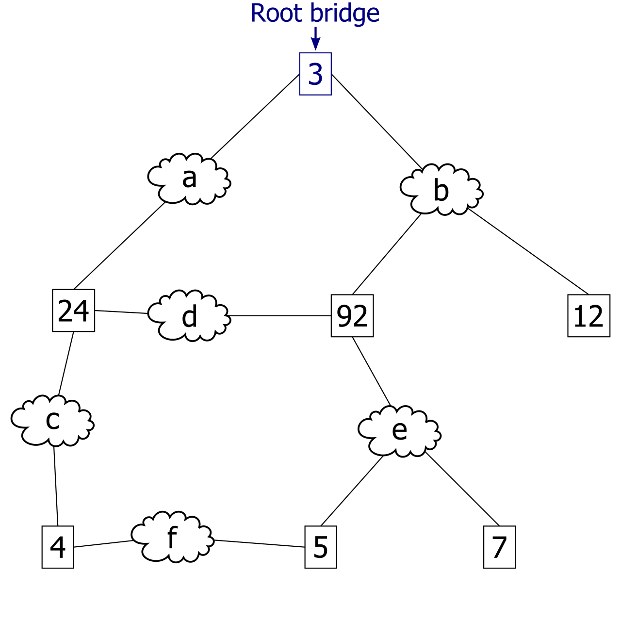
To accomplish this, switches constantly communicate in the background. Bridge Protocol Data Units (BPDUs) are multicast messages exchanged by switches to share Spanning Tree Protocol topology information. Through these BPDUs, the network elects a "king" to serve as the undisputed center of the map. The root bridge in a Spanning Tree Protocol topology acts as the central reference point for all optimal path calculations.
The Root Bridge Election
How do switches decide who becomes the root? Spanning Tree Protocol elects a root bridge based on the lowest overall Bridge ID.
A Spanning Tree Protocol Bridge ID consists of a bridge priority value combined with the switch's MAC address.
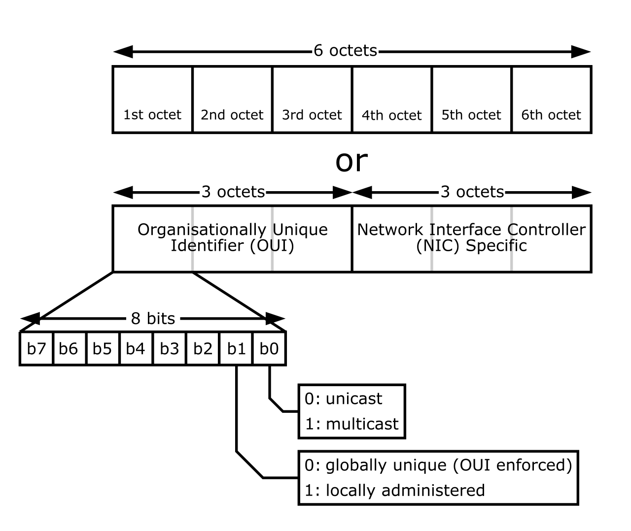
By design, the default Spanning Tree Protocol bridge priority for a standard switch is 32768. If you unpack a dozen switches from their boxes and plug them together, they will all proudly announce this identical priority. When this tie occurs, the protocol falls back to hardware addresses: if multiple switches share the same Spanning Tree Protocol bridge priority, the switch with the lowest MAC address becomes the root bridge. Because MAC addresses are assigned sequentially by manufacturers over time, the "lowest" MAC address generally belongs to the oldest piece of hardware. Without administrative intervention, your legacy, decade-old switch buried in a closet will quietly become the computational center of your modern network—a classic troubleshooting scenario.
The Anatomy of STP Port States
Once the root bridge is established, every other switch must find its shortest path to the center.
- Spanning Tree Protocol root ports are the specific ports on non-root switches that have the lowest path cost to the root bridge. Every non-root switch has exactly one root port.
- Spanning Tree Protocol designated ports are the assigned ports that forward traffic onto a specific network segment.
- To prevent the broadcast storm, the remaining redundant paths must be neutralized. Spanning Tree Protocol blocking ports intentionally discard data frames to prevent infinite network loops.
When a cable is plugged into a switch, the port does not immediately begin forwarding traffic. It must carefully observe the network to ensure it isn't creating a loop. The classic Spanning Tree Protocol port states are blocking, listening, learning, forwarding, and disabled.
The transition through these states is highly deliberate. For example, a switch port in the Spanning Tree Protocol learning state passively populates the MAC address table by observing source addresses, but to remain safe, a switch port in the Spanning Tree Protocol learning state actively drops user data frames. Only when it is absolutely certain the path is loop-free does the port fully awaken. A switch port in the Spanning Tree Protocol forwarding state can send and receive both BPDUs and standard user data frames.
Because this classic transition takes up to 50 seconds—an eternity in modern computing—engineers developed an upgrade. Rapid Spanning Tree Protocol (RSTP) reduces port transition times to sub-second levels compared to classic Spanning Tree Protocol, minimizing network downtime during topology changes.
While STP dictates the physical geometry of the network, VLANs dictates the logical boundaries. Virtual Local Area Networks (VLANs) logically separate broadcast domains on a single physical switch, allowing you to isolate IP phones, accounting computers, and guest Wi-Fi on the same exact hardware.
When a technician misconfigures an endpoint's connection, isolation becomes an outage. An incorrect VLAN assignment on a switch access port prevents the connected device from communicating with its intended logical network. The device might have perfect physical connectivity, but it is shouting into an empty, isolated room.
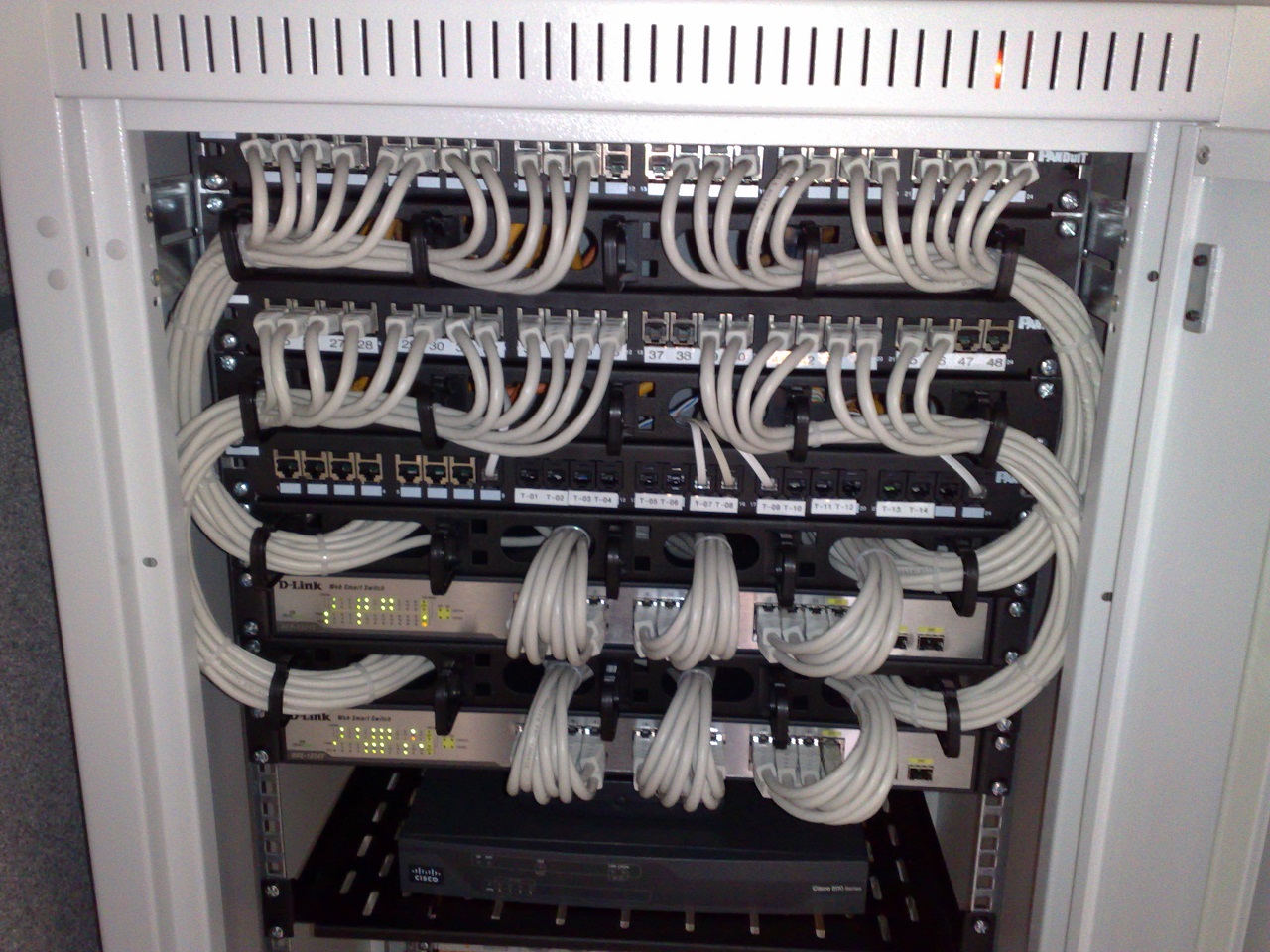
When we need VLANs to span across multiple switches, we aggregate the links. A VLAN trunk port carries aggregated traffic for multiple VLANs using 802.1Q tags. These tags act as colored labels for packets. However, every trunk port has a "native" VLAN reserved for untagged traffic. A severe, often difficult-to-diagnose anomaly occurs when the native VLANs on opposite ends of a trunk do not match. A native VLAN mismatch between two connected trunk ports causes untagged traffic to silently cross into the wrong logical broadcast domain. Because this happens without triggering obvious interface down states, it is a critical blind spot for junior administrators.
If Layer 2 is a single building, Layer 3 (Network Layer) is the global postal system. Routers do not care about MAC addresses or broadcast domains; they care about IP subnets and destination networks.
When a packet arrives at a router, the router consults its ledger. A routing table directs packets to their next destination based on the longest matching subnet mask of the destination IP address. The router seeks the most specific, precise mathematical match for the destination.
But what if the router has never heard of the destination? It utilizes a catch-all. A default route defines the exact gateway where a router sends a packet if no specific route matches the destination IP address. Without this, global communication fails entirely. A missing default route prevents a device from communicating with unknown external networks like the public Internet.
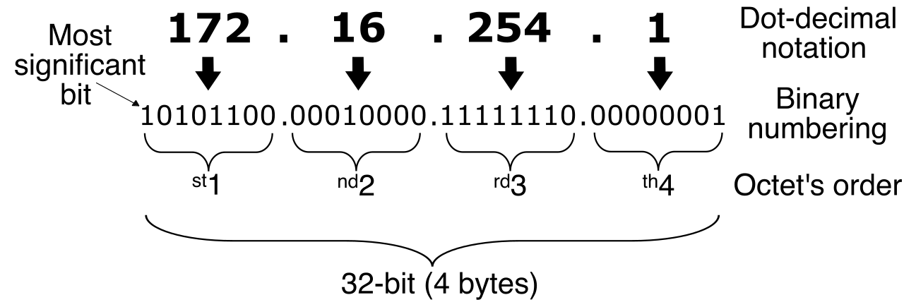
Mathematical Notation: The standard IPv4 default route is mathematically represented as 0.0.0.0/0. This denotes a network of all zeros and a subnet mask of zero, meaning "literally any IP address not explicitly defined elsewhere."
Routing Loops and the Self-Destruct Mechanism
Just as switches can suffer Layer 2 loops, routers can suffer Layer 3 loops. Routing loops occur when routers forward a packet endlessly among themselves due to conflicting routing table entries. (Router A thinks the destination is behind Router B; Router B thinks it is behind Router A).
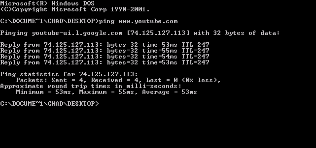
Because Layer 3 lacks the centralized root-bridge topology of STP, it relies on a fail-safe built directly into the IP packet header itself. The Time to Live (TTL) field in an IP packet prevents the packet from circulating infinitely in a Layer 3 routing loop. It acts as a countdown timer.
A router decrements the Time to Live (TTL) value of an IP packet by one unit before forwarding the packet to the next hop. If the packet is trapped in a loop, the TTL inevitably bleeds down to zero. A router drops an IP packet and sends an ICMP Time Exceeded message if the packet's Time to Live (TTL) value reaches exactly zero.
We cleverly exploit this exact ICMP fail-safe for diagnostics. The traceroute utility identifies the exact router path and helps administrators pinpoint the exact hop where routing fails by intentionally sending packets with progressively increasing TTL values (1, then 2, then 3...) and recording which routers generate the ICMP Time Exceeded errors.
The Subnet Mask: The Local Horizon
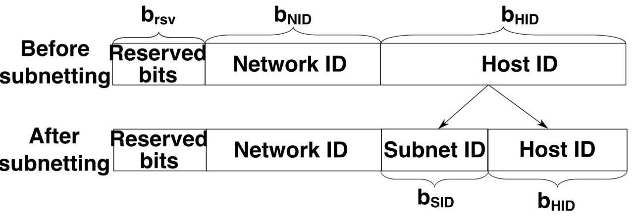
Endpoints must constantly decide whether to send traffic directly to a local peer (via Layer 2 switching) or hand it off to a router (via Layer 3 routing). They make this decision entirely based on their own IP address and subnet mask.
If an administrator misconfigures this mask, the endpoint's perception of reality fractures:
- An excessively large subnet mask can cause a device to erroneously assume a remote destination is located on the local physical network. The device will vainly send ARP requests into its local switch for an IP that is halfway across the world, failing to communicate.
- Conversely, an excessively small subnet mask can force a device to needlessly send local subnet traffic directly to the default gateway. The router must then clumsily reflect the traffic back onto the local network, wasting bandwidth and processing power.
The Default Gateway
When the endpoint correctly calculates that a destination is foreign, it needs an exit door. A default gateway serves as the primary exit point for devices attempting to reach IP addresses outside their local subnet.
When diagnosing an endpoint that can reach local file servers but cannot browse the internet, verify its gateway. A faulty default gateway configuration on a client prevents the client device from communicating with any remote subnets.
How do we quickly test this? The ping utility tests basic network connectivity to a default gateway by utilizing ICMP Echo Request and Echo Reply messages. If pinging the gateway fails, your troubleshooting remains strictly local. If it succeeds, the issue lies further downstream in the routing infrastructure.
Network troubleshooting often concludes at the application services responsible for allocating the IP addresses themselves. Dynamic Host Configuration Protocol (DHCP) is the lifeblood of client connectivity, and it operates under strict constraints.
Exhaustion and Rogue Servers
A DHCP server has a finite pool of addresses to lease. If a network segment experiences high turnover—like a busy coffee shop or a university lecture hall—the server may run dry. DHCP address pool exhaustion occurs when a DHCP server has zero available IP addresses left to lease to network clients. Instead of permanently expanding the subnet (which requires vast re-engineering), network administrators can resolve frequent DHCP pool exhaustion by significantly reducing the DHCP lease time duration. If leases expire in two hours instead of eight days, addresses are rapidly reclaimed from devices that have long since left the building.
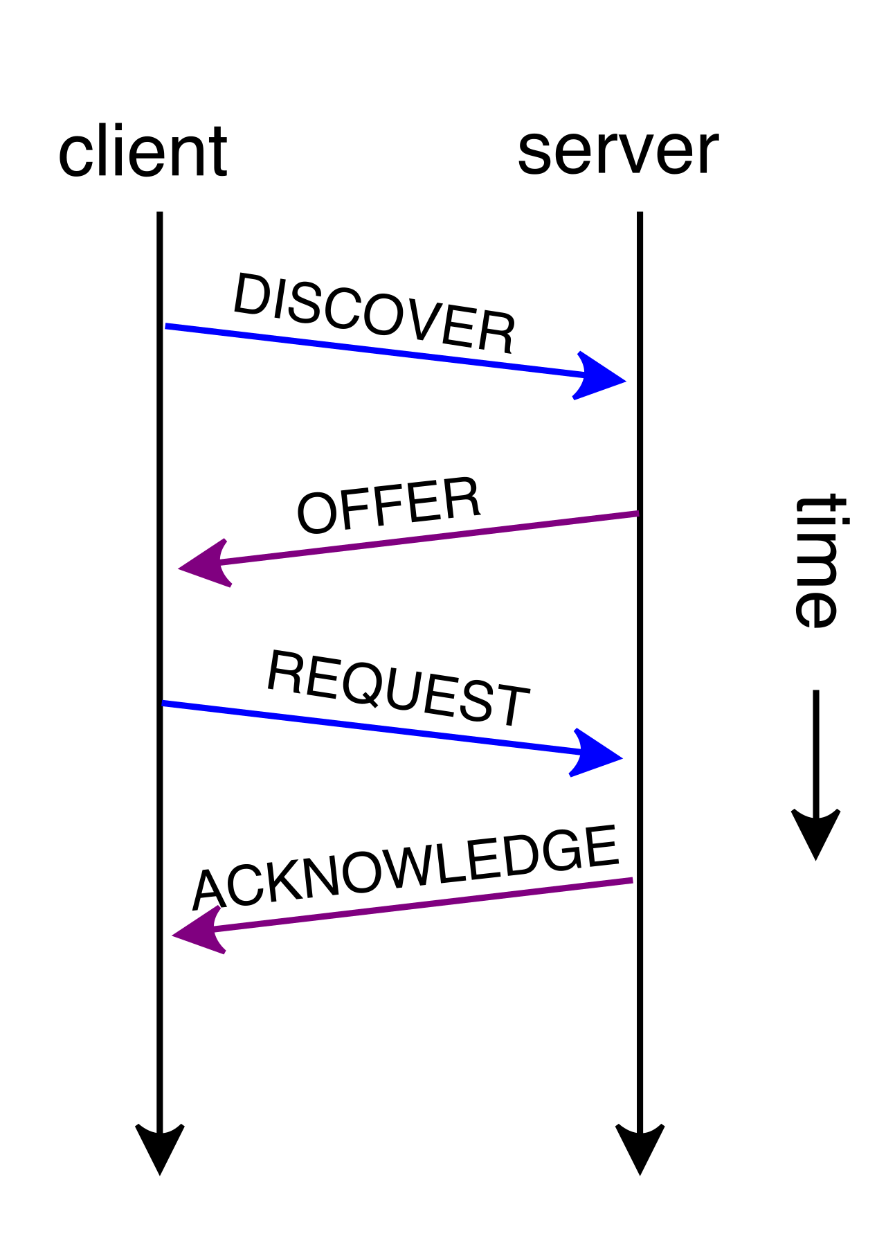
Sometimes, the threat isn't a lack of DHCP, but an imposter. A rogue DHCP server is an unauthorized network device that hands out incorrect IP configurations to legitimate clients. A user innocently plugging a home Wi-Fi router into an office Ethernet jack can inadvertently hijack traffic, handing out default gateways that lead to nowhere.
The Fallback: APIPA
What happens to a client when DHCP pool exhaustion occurs, or a rogue server is absent, and the legitimate server is down? The operating system refuses to simply give up. A Windows client automatically generates an Automatic Private IP Addressing (APIPA) address when the client fails to contact a DHCP server.
This is a critical diagnostic indicator. Automatic Private IP Addressing (APIPA) addresses fall strictly within the 169.254.0.0/16 subnet range. The moment you type [ipconfig](https://en.wikipedia.org/wiki/ipconfig) and see an IP beginning with 169.254, you instantly know the problem isn't the client's internal hardware; it is a systemic failure to reach a DHCP service.
Duplicate IP Addresses
Finally, we confront the paradox of duplication. An IP address must be entirely unique within its network. Duplicate IP addresses occur when two separate devices on the same network segment are configured with the identical IPv4 address. This usually happens when an administrator statically assigns an IP that DHCP is simultaneously trying to lease.
The resulting behavior is chaotic. Duplicate IP addresses cause intermittent connectivity drops because switch MAC tables constantly overwrite the associated physical port. As both devices attempt to communicate using the same IP, the underlying Layer 2 infrastructure becomes utterly confused about where to deliver the returning frames.
To prevent this civil war, modern endpoints proactively sweep the network before claiming an IP. Address Resolution Protocol (ARP) probing is used by modern operating systems to detect duplicate IP addresses on a local subnet. If the operating system sends an ARP probe for its intended IP and receives a reply, it immediately flags a conflict, disables its interface, and protects the network from localized collapse.