Cabling and Interface Issues
Not sure you’re ready?
Take the ~3-minute readiness diagnostic and see where you stand.
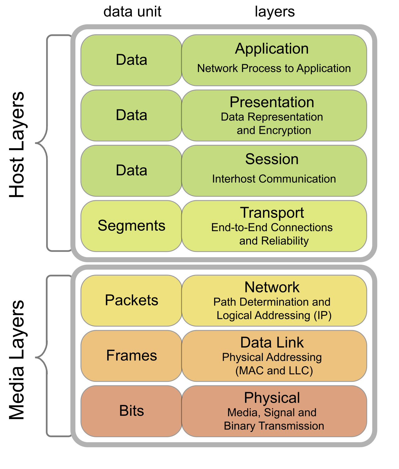
A digital packet carrying a multi-million-dollar financial transaction is ultimately nothing more than a series of voltage spikes on a copper wire or flashes of light traversing a glass filament. If the physical medium is flawed, the highest layers of encryption, routing protocols, and application logic are entirely useless. At the physical layer—Layer 1 of the OSI model—physics governs communication. Network engineering begins by controlling electrical impulses and light waves, ensuring they arrive at their destination precisely as they were sent. When these physical transmissions degrade or fail entirely, the network administrator must possess the precise diagnostic tools and theoretical understanding to isolate the fault.
To transmit data across physical space, we rely on two primary mediums: fiber optic strands that carry photons, and twisted pair copper cables that carry electrons. Each has strict architectural limits dictated by physics, and violating these limits results in catastrophic network failure.
Fiber Optic Engineering
Fiber optic network cables use light signals and are completely immune to electromagnetic interference and crosstalk. Because they do not rely on electrical currents, they cannot be disturbed by nearby magnetic fields. There are two entirely different architectures for fiber transmission, engineered for distinct purposes:
- Single-mode fiber optic cable uses a highly focused laser light source for data transmission. Because the core is incredibly narrow, light travels in a single straight path without bouncing off the internal walls. Consequently, single-mode fiber optic cable is designed to support high-bandwidth transmissions over long-distance network links, spanning kilometers between geographical campuses or telecommunications facilities.
- Multimode fiber optic cable uses Light Emitting Diodes (LEDs) as a light source for data transmission. It features a wider core that allows multiple beams (modes) of light to bounce along the internal walls. Due to the dispersion of these light beams, multimode fiber optic cable is designed exclusively for short-distance network connections such as inter-rack wiring in a data center.
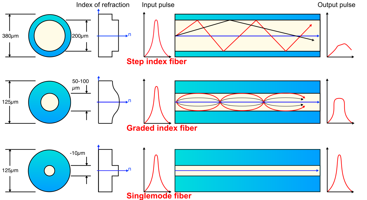
A common and highly destructive error occurs during network upgrades when transceivers and cables are mixed. Connecting a single-mode fiber transceiver to a multimode fiber cable causes severe signal loss and link failure. The narrow, intense laser light from the single-mode optic disperses wildly inside the wide multimode glass core, failing to reach the opposite end with sufficient intensity.
Furthermore, fiber optic communication is directional. A Tx/Rx reversal is a cabling fault that occurs when the transmit (Tx) fiber optic strand is incorrectly plugged into the transmit port on the remote transceiver rather than the receiving (Rx) port. Light must always travel from a transmitter to a receiver; firing two lasers at one another yields a blind, silent link.
Copper Cable Standards and Shielding
While fiber optics are immune to interference, copper cabling must actively defend against it. External electrical noise from the environment can induce unwanted currents onto copper wires, corrupting ongoing data transmissions. This is known as Electromagnetic Interference (EMI).
To mitigate EMI, network architects must choose the correct cable shielding and category:
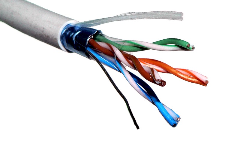
- Unshielded Twisted Pair (UTP) cable lacks protective metallic shielding against external electromagnetic interference. It is cost-effective, flexible, and serves as the standard choice for general office environments.
- Shielded Twisted Pair (STP) cable incorporates metallic foil or braided wire to protect against external electromagnetic interference. This grounded barrier absorbs ambient electromagnetic energy before it can reach the internal data-carrying wires. STP cable is required in physical environments with heavy electrical machinery or fluorescent lighting to prevent signal corruption.
Beyond shielding, copper cables are manufactured to strict architectural standards to support specific frequencies and speeds.
| Cable Category | Maximum Data Rate | Maximum Distance |
|---|---|---|
| Category 5 | 100 Megabits per second | 100 meters |
| Category 5e | 1 Gigabit per second | 100 meters |
| Category 6 | 10 Gigabits per second | 55 meters |
| Category 6a | 10 Gigabits per second | 100 meters |
A network's operational speed is always bound by the physical capabilities of its weakest link. Using lower-category copper cables for higher-speed network requirements introduces severe data transmission errors and dropped frames. You cannot successfully push 10 Gigabits per second of frequency across an old Category 5 installation without overwhelming the electrical properties of the wire.
Even with the correct cable category, copper cables must be terminated precisely. Historically, the sequence of the internal wire pins dictated how devices could communicate.
- A straight-through twisted pair cable is traditionally required to connect unlike network devices, such as a computer to a network switch. The transmit pins on the computer perfectly align with the receive pins on the switch.
- A crossover twisted pair cable is traditionally required to connect like network devices, such as connecting two network switches directly together. Because both switches use the exact same transmit pins, the cable must internally cross the transmit path over to the receive path.
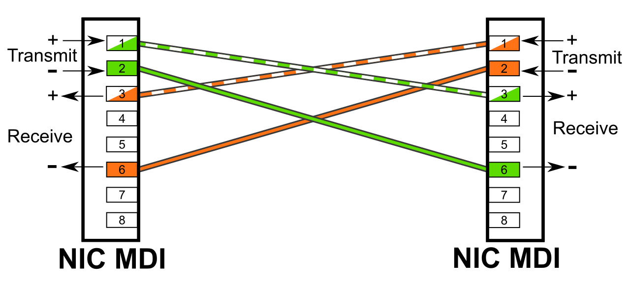
Fortunately, modern networking equipment largely mitigates this complexity via Auto-MDIX technology. Auto-MDIX automatically detects and configures the correct transmission pins on a network port regardless of whether a straight-through or crossover cable is used.
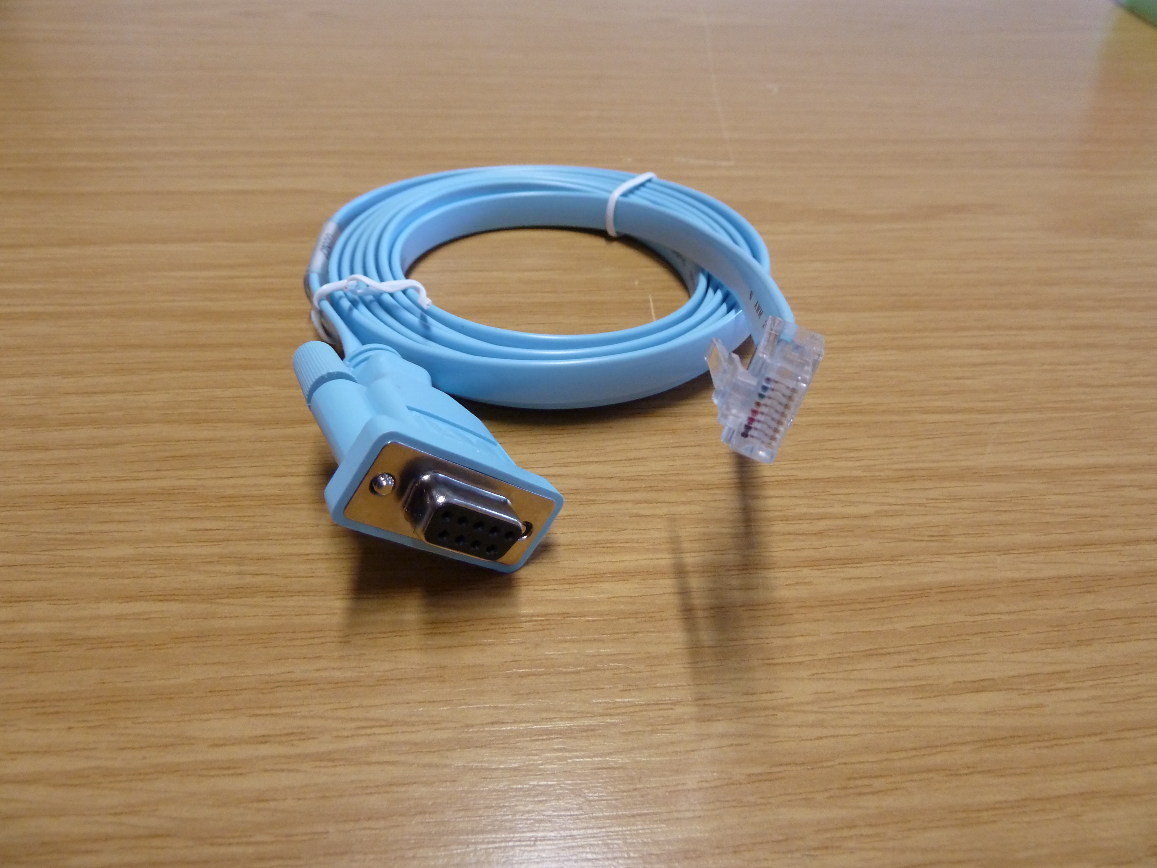
There is also a third, highly specific pinout: the rollover cable. A rollover cable is specifically used to connect a computer serial port to the local console management port of a router or switch. It is entirely for out-of-band administrative management, not for transmitting Ethernet traffic.
Circuit and Wiring Errors
When a cable is physically damaged or poorly terminated by a technician, severe electrical faults occur.
- An open circuit fault in a network cable indicates a physical break in the internal wire strand. The electrical path is severed, and no current can flow.
- Conversely, a short circuit fault in a network cable occurs when two bare electrical conductors touch and create an improper electrical path. The signal escapes its intended lane, immediately destroying the integrity of the transmission.
A far more insidious termination mistake is the split pair wiring error. Inside a twisted pair cable, specific pairs of wires are twisted together at mathematically precise intervals to cancel out ambient electromagnetic noise. A split pair wiring error occurs when an administrator mistakenly combines two wires from different twisted pairs to form a single transmission circuit. While end-to-end electrical continuity might theoretically exist (allowing a basic wire-mapper tool to falsely report success), split pair wiring errors completely defeat the electromagnetic noise-canceling effect of twisted pair cables. The resulting link will be highly unstable, choked by interference.
Attenuation and Crosstalk
As signals travel across a physical medium, they are subjected to the laws of entropy.
Attenuation is the gradual loss of signal strength as an electrical or optical transmission travels over a physical distance.
Signal attenuation and insertion loss are measured in mathematical units called decibels (dB). When planning a network, administrators calculate the "loss budget" to ensure the signal remains readable by the receiving equipment. Signal attenuation on copper network cables increases significantly and disrupts network traffic if the cable length exceeds the 100-meter architectural standard.
Another primary source of signal degradation is crosstalk. Crosstalk is the unwanted transfer of electromagnetic signals from one wire pair to an adjacent wire pair within the exact same network cable. It is the electrical equivalent of two people standing in an echoing room, each trying to hold a separate conversation—eventually, the voices bleed together.
- Near-End Crosstalk (NEXT) occurs when a transmitted signal actively interferes with a received signal at the exact same termination end of the cable link. Near-End Crosstalk is most frequently caused by an installer untwisting the wire pairs too far back when attaching the RJ-45 connector. Removing the twist removes the noise cancellation exactly where the transmit signal is at its strongest.
- Far-End Crosstalk (FEXT) is the electromagnetic interference measured at the opposite end of a cable from where the transmission originally started.
When physical faults are suspected, network administrators deploy specialized reflectometry tools that function essentially like radar for cables.
To interrogate copper infrastructure, a Time Domain Reflectometer (TDR) locates physical breaks and impedance faults in copper network cables by sending an electrical pulse and measuring the reflection time. If a cable is supposed to be 50 meters long, but the TDR pulse reflects back at 15 meters, the administrator knows precisely where the wire was cut or severed.
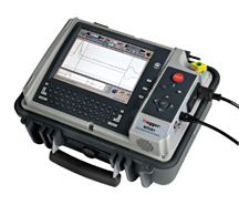
To interrogate fiber optic infrastructure, an Optical Time Domain Reflectometer (OTDR) is utilized. An OTDR locates breaks and splice faults in fiber optic cables by measuring backscattered light. As a photon pulse travels down the glass core, minute imperfections or severed glass send tiny fragments of light backward. The OTDR captures these backscatters, mapping out the exact geographical location of severe attenuation, poor optical splices, or physical breaks.
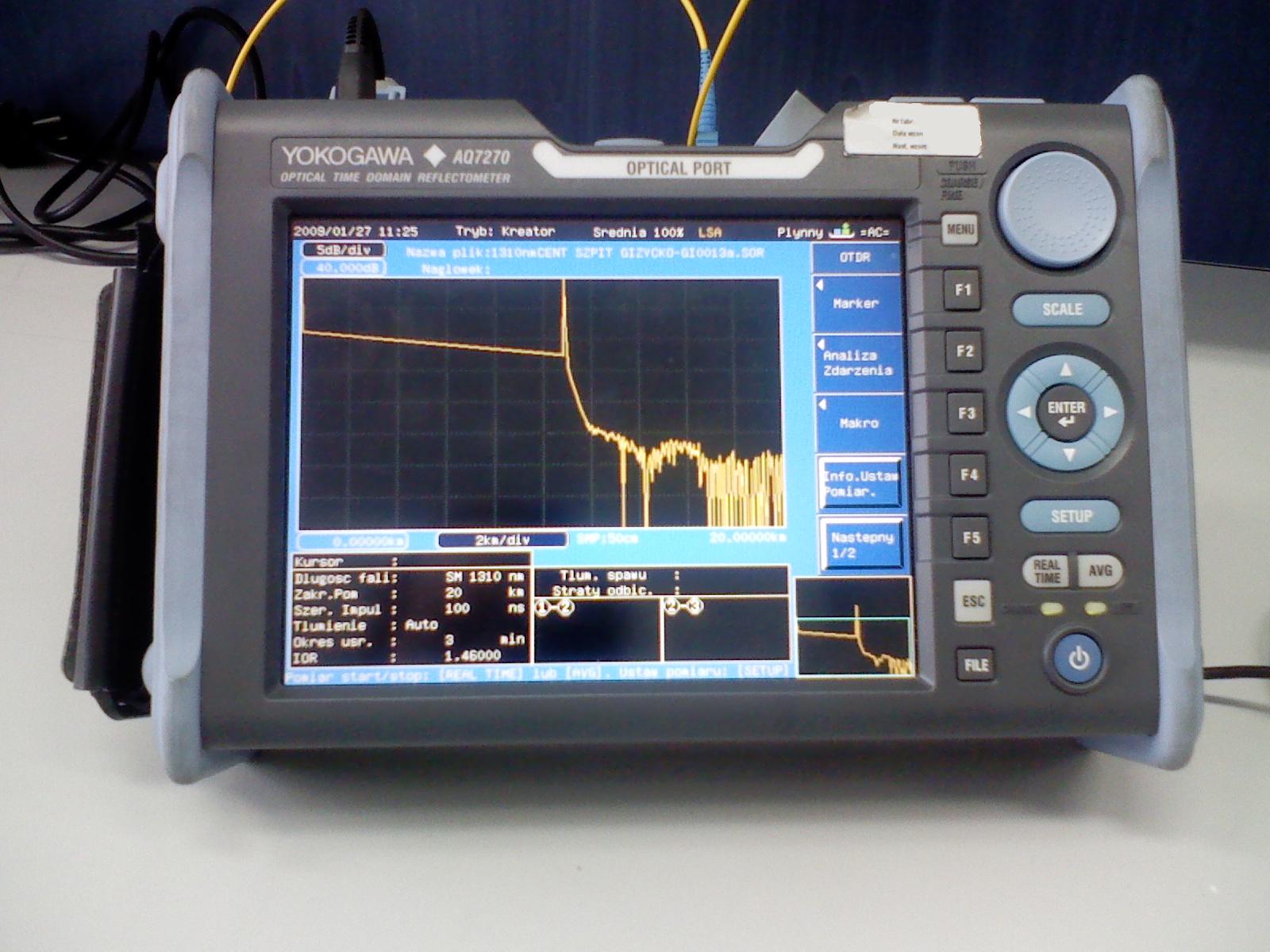
You will rarely witness a physical cable break as it happens. Instead, physical layer problems reveal themselves as numerical anomalies on a router or switch. By logging into the network device and analyzing the interface counters, an administrator can reverse-engineer the physical fault occurring over the wire.
Corrupt and Malformed Frames
The most telling metric of physical layer decay is the CRC counter. Cyclic Redundancy Check (CRC) errors on a switch interface explicitly indicate that an Ethernet frame was corrupted at some point during physical transmission. The switch performs a mathematical calculation on the incoming frame; if the result does not match the checksum attached by the sender, the frame has been damaged in transit and is discarded. A high continuous rate of Cyclic Redundancy Check errors on a switch port strongly points to a damaged network cable or intense environmental electrical noise.

Administrators must also monitor for anomalous frame sizes, which tell a specific story about protocol and configuration alignment:
- A runt is an Ethernet frame that is smaller than the minimum legal Ethernet size of 64 bytes. Runt frames are most commonly caused by network collisions in outdated half-duplex legacy network environments. The transmission is literally smashed to pieces before the full frame can be dispatched.
- Conversely, a giant is an Ethernet frame that exceeds the standard maximum untagged Ethernet frame size of 1518 bytes. Giant frames are frequently caused by mismatched Maximum Transmission Unit (MTU) configurations between two connected network devices. If a server assumes it is permitted to send a 9000-byte "jumbo frame," but the switch port is strictly configured for 1518 bytes, the switch will record a giant and drop the oversized traffic.
Drops and Administrative States
Not all discarded packets represent electrical failure. Interface drops occur when a network switch intentionally discards incoming or outgoing packets due to heavily congested port memory buffers. If a 10-Gigabit uplink attempts to blast traffic down a 1-Gigabit access port faster than the access port can process it, the memory buffers fill up, and the excess packets fall to the floor.
Likewise, an inactive link does not always mean a severed cable. An administratively down interface status strictly means a network administrator has manually disabled the port via software configuration commands (such as typing shutdown on a Cisco interface). Do not spend hours hunting for a broken cable when the port has simply been turned off in the operating system.
Finally, two of the most disruptive physical configuration issues occur not because of damaged wiring, but because the two network endpoints fundamentally disagree on how they are going to communicate.
First, consider the speed configuration. A physical speed configuration mismatch between two directly connected network interfaces prevents the communication link from establishing entirely. If one side is hardcoded to 1000 Mbps and the opposite side is hardcoded to 100 Mbps, the ports will fail to synchronize their encoding mechanisms, resulting in a dead link.
Even more insidious is the duplex mismatch. A duplex mismatch occurs when one end of a network link operates in full-duplex mode (capable of transmitting and receiving simultaneously) while the opposite end operates in half-duplex mode (capable of only transmitting or receiving at one time).
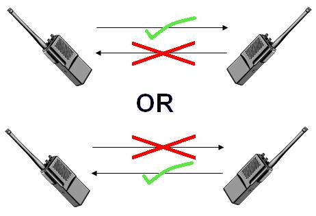
Unlike a speed mismatch, a duplex mismatch allows the physical link to establish. The link lights will illuminate green, tricking a novice technician into believing the connection is healthy. However, it results in severely degraded network performance and a rapid accumulation of late collisions. The full-duplex side will eagerly transmit data at the exact same moment the half-duplex side is transmitting, destroying the electrical signals on the wire. The resulting retransmissions will cripple network throughput, proving once again that a profound understanding of Layer 1 principles is the ultimate requirement for maintaining network integrity.