OSI Reference Model
Not sure you’re ready?
Take the ~3-minute readiness diagnostic and see where you stand.
Imagine an international supply chain where a manufacturing plant in Tokyo must deliver highly sensitive, encrypted blueprints to a laboratory in Berlin. The engineers who draw the blueprints do not build the shipping containers, the dock workers who load the containers do not encrypt the blueprints, and the truck drivers do not negotiate international customs treaties. Instead, a strict hierarchy of independent systems works in concert. Each tier performs a specific, specialized task before handing the payload off to the next.

In computer networking, this exact separation of concerns is formalized by the OSI reference model, which consists of exactly seven conceptual layers. The acronym OSI stands for Open Systems Interconnection. Created by the International Organization for Standardization (ISO), the OSI model standardizes the communication functions of telecommunication and computing systems systems, ensuring that hardware and software from different vendors can seamlessly interoperate.
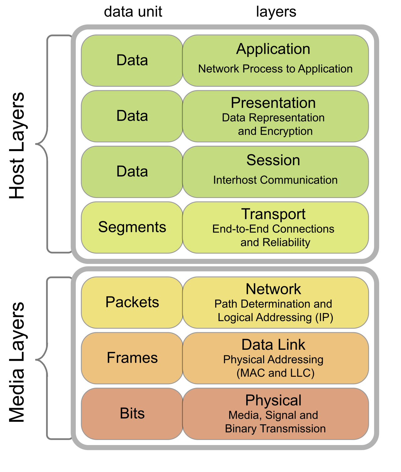
For the network support technician or systems administrator, the OSI model is not merely an academic theory; it is the ultimate diagnostic map. When a user complains that "the internet is down," the OSI model provides the structured workflow to determine if the failure is a severed physical cable, a misconfigured router, or a crashed web server.
Before examining the individual layers, we must understand how data traverses this model. When an application on one computer wants to send data to another, that data travels down the seven layers on the sending machine and up the seven layers on the receiving machine.
Encapsulation is the process of adding layer-specific protocol headers to data as the data moves down the OSI model layers.
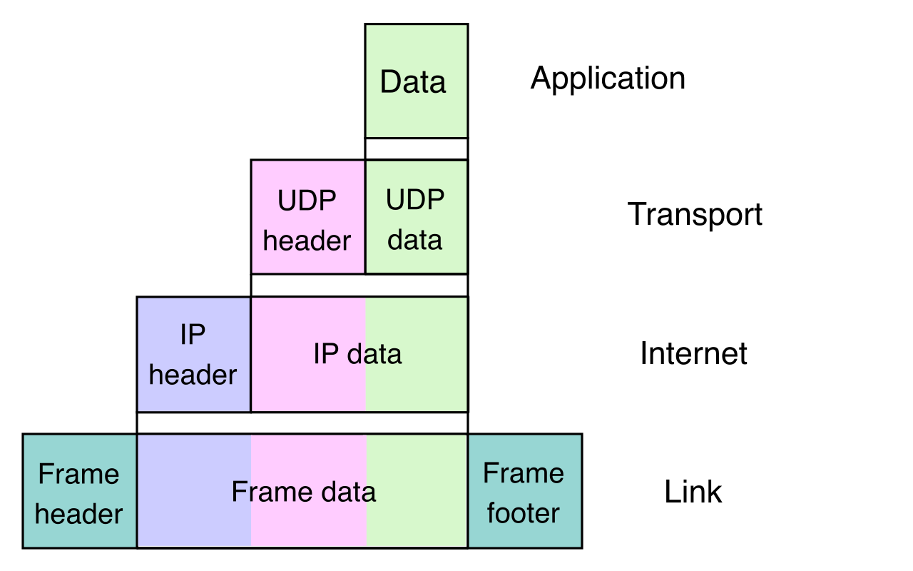
Think of encapsulation like placing a letter inside an envelope, placing that envelope inside a larger shipping box, and sticking a routing label on the outside. Each layer adds its own specific instruction header so the equivalent layer on the receiving end knows what to do with it.
Decapsulation is the process of stripping layer-specific protocol headers from data as the data moves up the OSI model layers.
When the data reaches its destination, the receiving machine works in reverse. It reads the outermost header, processes the instructions, strips the header off, and passes the remaining payload up to the next layer until the original data is presented to the receiving application.
At each layer, the resulting package of data and headers is called a Protocol Data Unit (PDU). The name of the PDU changes as it moves through the model, reflecting its current state of encapsulation.
The top three layers of the OSI model deal heavily with application-level software. They prepare the data for network transport but are largely divorced from the physical realities of cables and routers. Because these layers handle high-level information formatting, the Protocol Data Unit associated with the Application, Presentation, and Session layers is broadly categorized simply as data.
Layer 7: The Application Layer
Layer 7 of the OSI model is the Application layer. It is the closest layer to the end user. However, Layer 7 is not the application itself (like Google Chrome or Microsoft Outlook); rather, the Application layer provides network services directly to end-user software applications. It serves as the portal through which software accesses network resources.
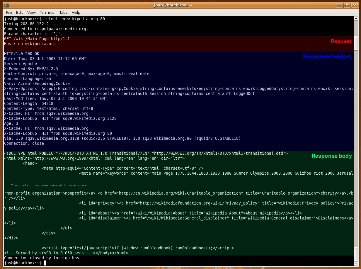
If a user is browsing a website, the Hypertext Transfer Protocol (HTTP) operates at the Application layer of the OSI model to request and receive the web pages. Similarly, if a system administrator is moving configuration files to a backup server, the File Transfer Protocol (FTP) operates at the Application layer of the OSI model to facilitate that transfer.
Layer 6: The Presentation Layer
Layer 6 of the OSI model is the Presentation layer. If Layer 7 dictates what network service is required, Layer 6 ensures the data is readable by the receiving system. The Presentation layer translates data into a standardized format for the Application layer.
This layer handles three critical operations that you encounter every day:
- Translation: Converting text encoding (like ASCII to UTF-8) so different operating systems can understand each other.
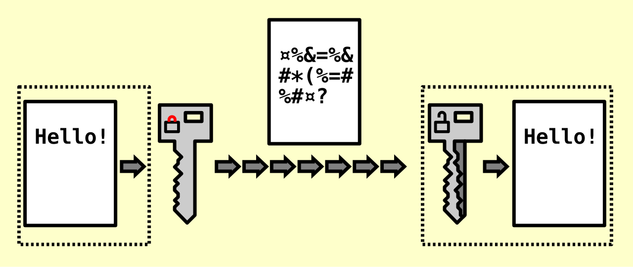
- Encryption and Decryption: The Presentation layer performs the encryption of network data (securing it before transmission) and performs the decryption of network data (unlocking it upon receipt). When you see the padlock in your browser, Layer 6 mechanics are at work.
- Compression: The Presentation layer performs data compression to optimize network transfer sizes, ensuring bandwidth is not wasted on bloated data structures.
Layer 5: The Session Layer
Layer 5 of the OSI model is the Session layer. Imagine making a telephone call; someone must dial the number, someone must answer, both parties must keep the line open while talking, and eventually, someone must hang up.
The Session layer handles this exact lifecycle for software. The Session layer establishes network communication connections between distinct applications on different hosts. Once established, the Session layer maintains ongoing network communication connections during data exchanges, handling synchronization and recovery if a brief interruption occurs. Finally, the Session layer gracefully terminates network communication connections upon the completion of a data exchange, ensuring resources are freed up on both servers.
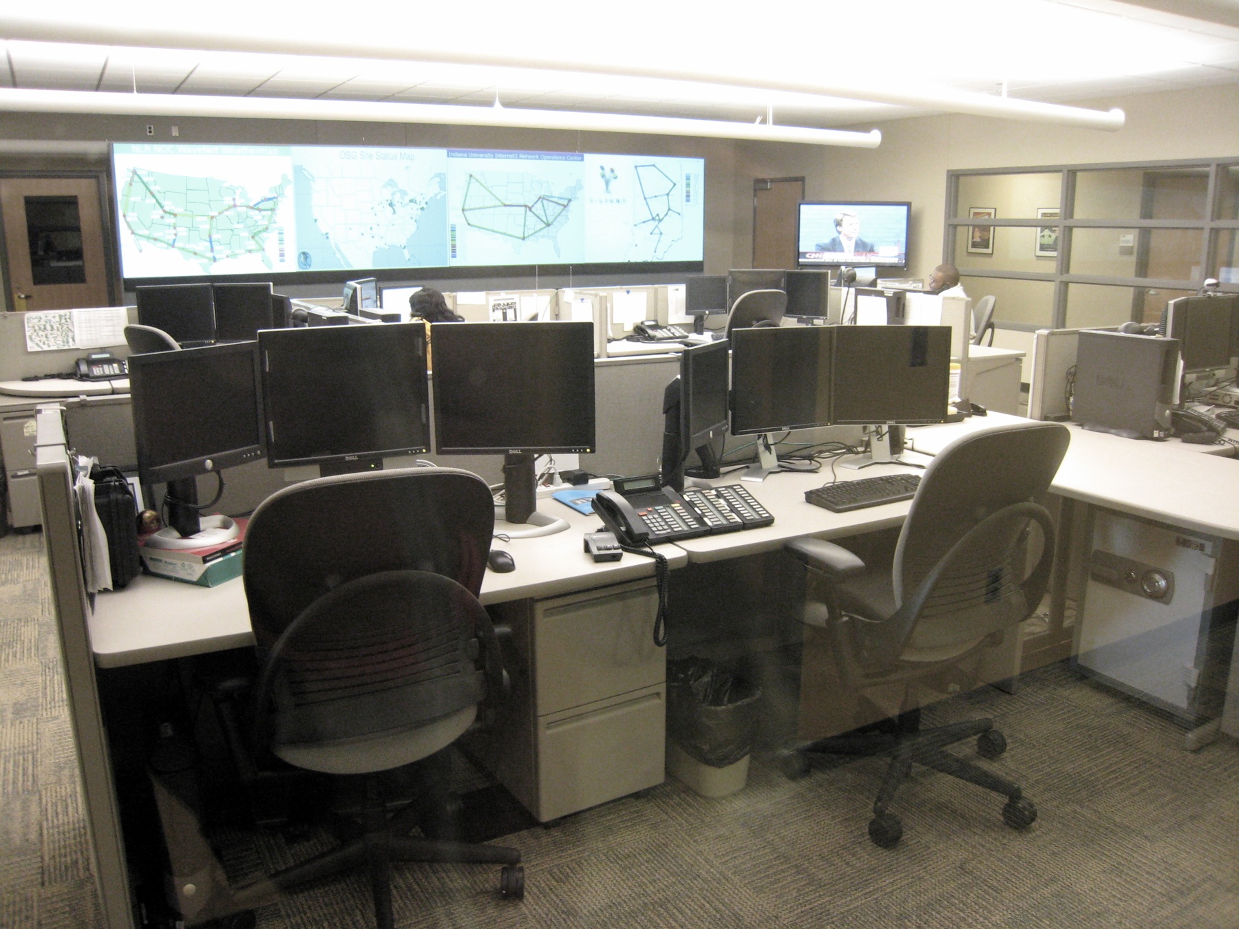
While the upper layers handle the meaning and formatting of the data, the bottom four layers handle the mechanics of delivery. This is the domain of infrastructure: the routers, switches, cables, and addressing schemes that make up the daily reality of a network operations center (NOC).
Layer 4: The Transport Layer
Layer 4 of the OSI model is the Transport layer. The Transport layer manages end-to-end communication between host applications. Its job is to take the data from the Session layer, break it into manageable pieces, and ensure it gets delivered to the correct specific application on the target machine.
It achieves this through two critical mechanisms:
- Multiplexing via Ports: A single server might simultaneously host a web site, an email service, and a file share. The Transport layer utilizes port numbers to multiplex network communications for different applications. This guarantees that inbound web traffic goes to the web server software (Port 80/443), while inbound email traffic goes to the mail server software (Port 25).
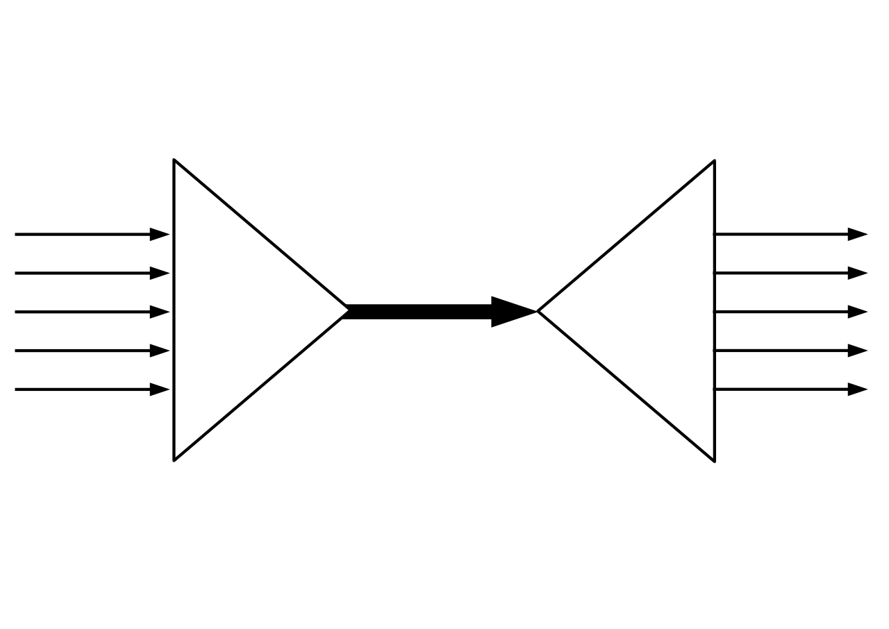
- Reliability and Flow Control: Imagine a high-powered server sending a massive file to a ten-year-old laptop. The laptop's network interface would drown in data. To prevent this, the Transport layer utilizes flow control to prevent a fast sender from overwhelming a slow receiver, dynamically adjusting the transmission speed.
The Protocol Data Unit changes names at this layer depending on the protocol used. The PDU for the reliable Transmission Control Protocol (TCP) at the Transport layer is the segment. Conversely, the PDU for the faster, connectionless User Datagram Protocol (UDP) at the Transport layer is the datagram.
Layer 3: The Network Layer
Layer 3 of the OSI model is the Network layer. If the Transport layer is about getting data to the right application, the Network layer is about getting data to the right computer, no matter where it is in the world.
The Network layer routes data across multiple distinct interconnected networks. It is the logical map of the internet. To navigate this map, the Network layer utilizes logical addressing to identify devices across different networks. This logical address allows networks to be grouped geographically or organizationally.
Internet Protocol (IP) addresses operate at the Network layer of the OSI model. When you ping an IP address to see if a server is online, you are testing Layer 3 connectivity. Because it must calculate the best path through the global internet maze, network routers operate at the Network layer of the OSI model, reading IP addresses and forwarding data closer to its final destination.
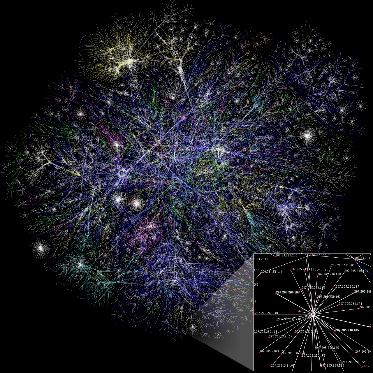
The Protocol Data Unit associated with the Network layer is the packet.
Layer 2: The Data Link Layer
Layer 2 of the OSI model is the Data Link layer. While Layer 3 (IP addressing) gets your data to the correct city and neighborhood, Layer 2 gets it to the exact front door. The Data Link layer provides node-to-node data transfer across a single physical network segment.
Instead of logical IP addresses, the Data Link layer uses Media Access Control (MAC) addresses to uniquely identify devices on a local network segment. A MAC address is a physical address burned into the network interface card at the factory.
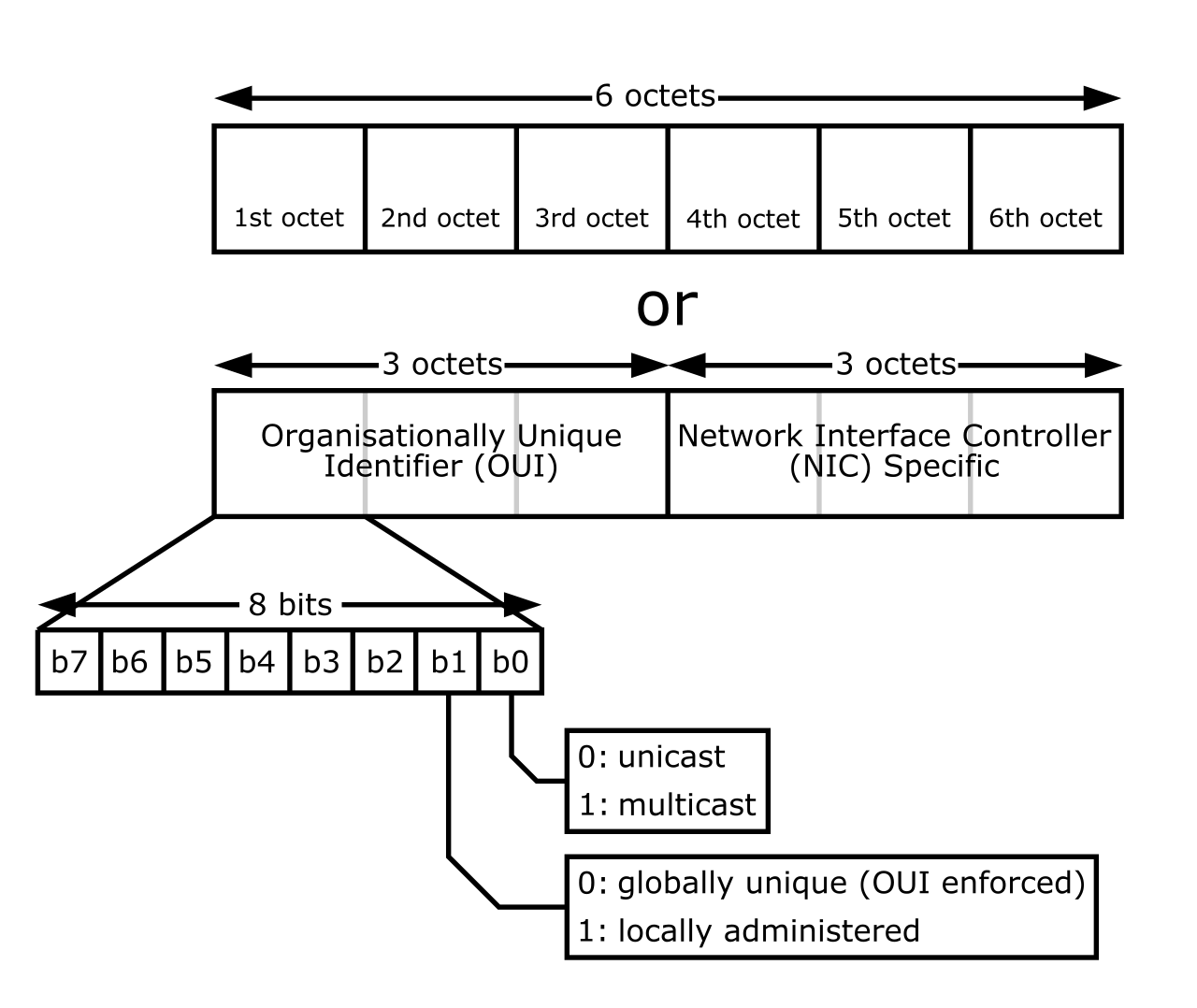
To manage both the interaction with the Network layer above it and the Physical layer below it, the Data Link layer is split into two distinct sublayers:
- The Data Link layer contains the Logical Link Control (LLC) sublayer, which interfaces with Layer 3 network protocols (like IP) and handles error checking.
- The Data Link layer contains the Media Access Control (MAC) sublayer, which dictates how devices gain permission to transmit data over the physical medium without colliding with one another.
Because they rely on MAC addresses to forward traffic directly to the correct connected device, network switches primarily operate at the Data Link layer of the OSI model.
The Protocol Data Unit associated with the Data Link layer is the frame.
Layer 1: The Physical Layer
Finally, we reach the bottom. Layer 1 of the OSI model is the Physical layer. All the high-level applications, logical IP routing, and MAC addressing mean nothing if we cannot physically move energy from one location to another.
The Physical layer converts data into raw bit streams—ones and zeros represented by electrical voltages on copper wire, pulses of light in fiber optic cables, or radio frequency waves in Wi-Fi. The Physical layer then transmits raw bit streams over a physical network medium.
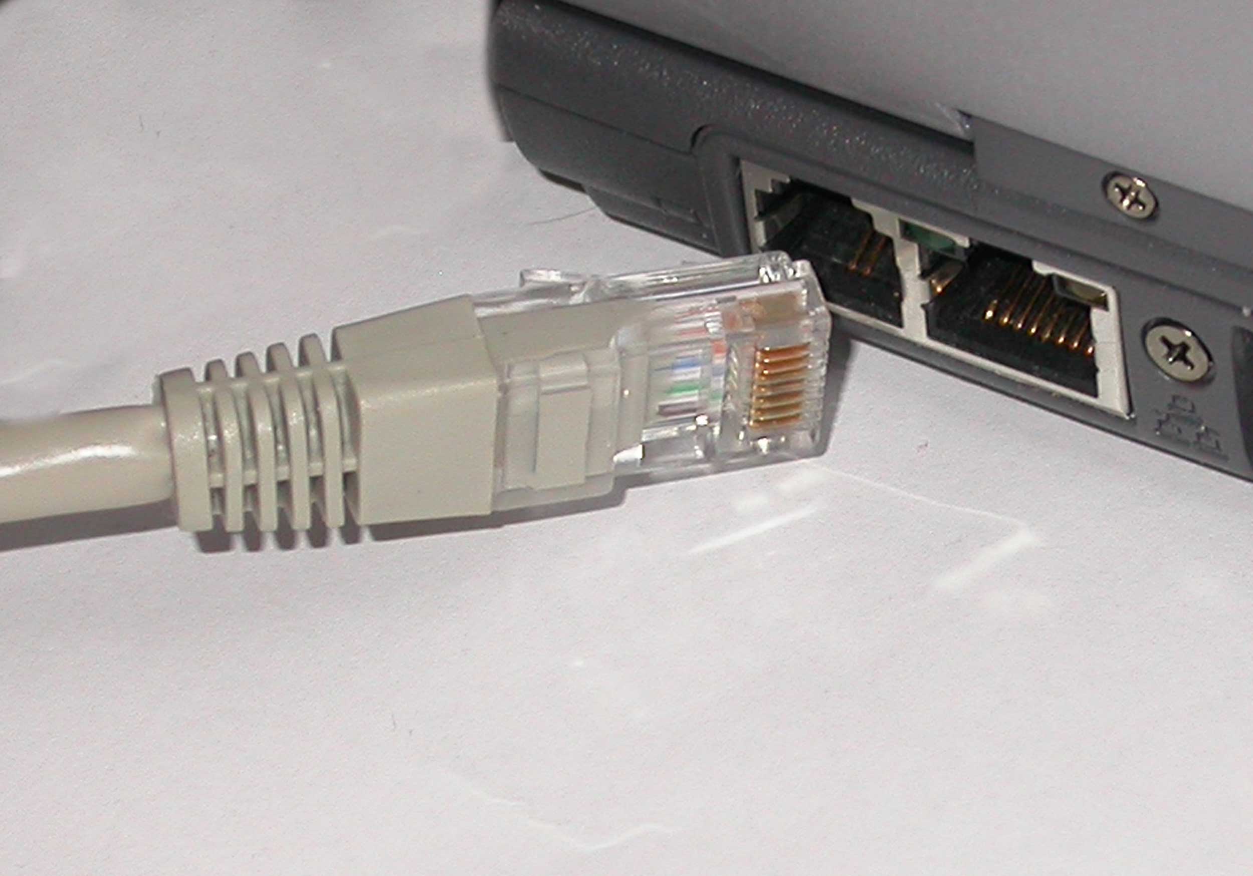
Because this layer is purely mechanical and electrical, it possesses no intelligence regarding addressing or data meaning. Consequently, network cables operate at the Physical layer of the OSI model, as do legacy devices like network hubs, which simply operate at the Physical layer by repeating an electrical signal out of all connected ports blindly.
The Protocol Data Unit associated with the Physical layer is the bit.
To validate your understanding for the CompTIA Network+ (N10-009) exam, commit the following PDU and layer associations to memory:
| OSI Layer | Layer Name | Core Function | Protocol Data Unit (PDU) | Key Devices / Protocols |
|---|---|---|---|---|
| 7 | Application | Provides network services to applications. | Data | HTTP, FTP, SMTP |
| 6 | Presentation | Translation, encryption, decryption, compression. | Data | SSL/TLS, JPEG, ASCII |
| 5 | Session | Establishes, maintains, and terminates connections. | Data | NetBIOS, RPC |
| 4 | Transport | End-to-end delivery, port multiplexing, flow control. | Segment (TCP) / Datagram (UDP) | TCP, UDP |
| 3 | Network | Logical addressing and routing across distinct networks. | Packet | Routers, IP Addresses |
| 2 | Data Link | Node-to-node delivery, local hardware addressing. | Frame | Switches, MAC Addresses |
| 1 | Physical | Converts data to raw bit streams for physical transmission. | Bit | Hubs, Cables, NIC Transceivers |
As an IT professional, you will use the OSI model daily to structure your troubleshooting.
A "Bottom-Up" troubleshooting approach starts at Layer 1: Is the network cable plugged in? Is the port on the switch lit up? If Layer 1 is good, you move to Layer 2: Is the switch configured correctly? Is the MAC address blocked? Then Layer 3: Can I ping the IP address? Is the router dropping the packet?
By isolating network failures to a specific layer of the OSI model, you remove the guesswork from your daily operations. You stop randomly rebooting servers and start systematically diagnosing the exact point of failure within the communication stack.