Network Appliances and Applications
Not sure you’re ready?
Take the ~3-minute readiness diagnostic and see where you stand.
A modern enterprise network operates precisely like the infrastructure of a dense metropolis. Data, like vehicular traffic, flows ceaselessly, requiring managed intersections, security checkpoints, specialized distribution hubs, and express lanes. For decades, constructing this infrastructure meant racking and cabling heavy, power-hungry, purpose-built machines. Today, the very same functions are just as likely to exist as pure code, executing silently in a virtualized data center. To master network operations, you must understand both the physical appliances you will hold in your hands and the virtual applications you will deploy from a command line.
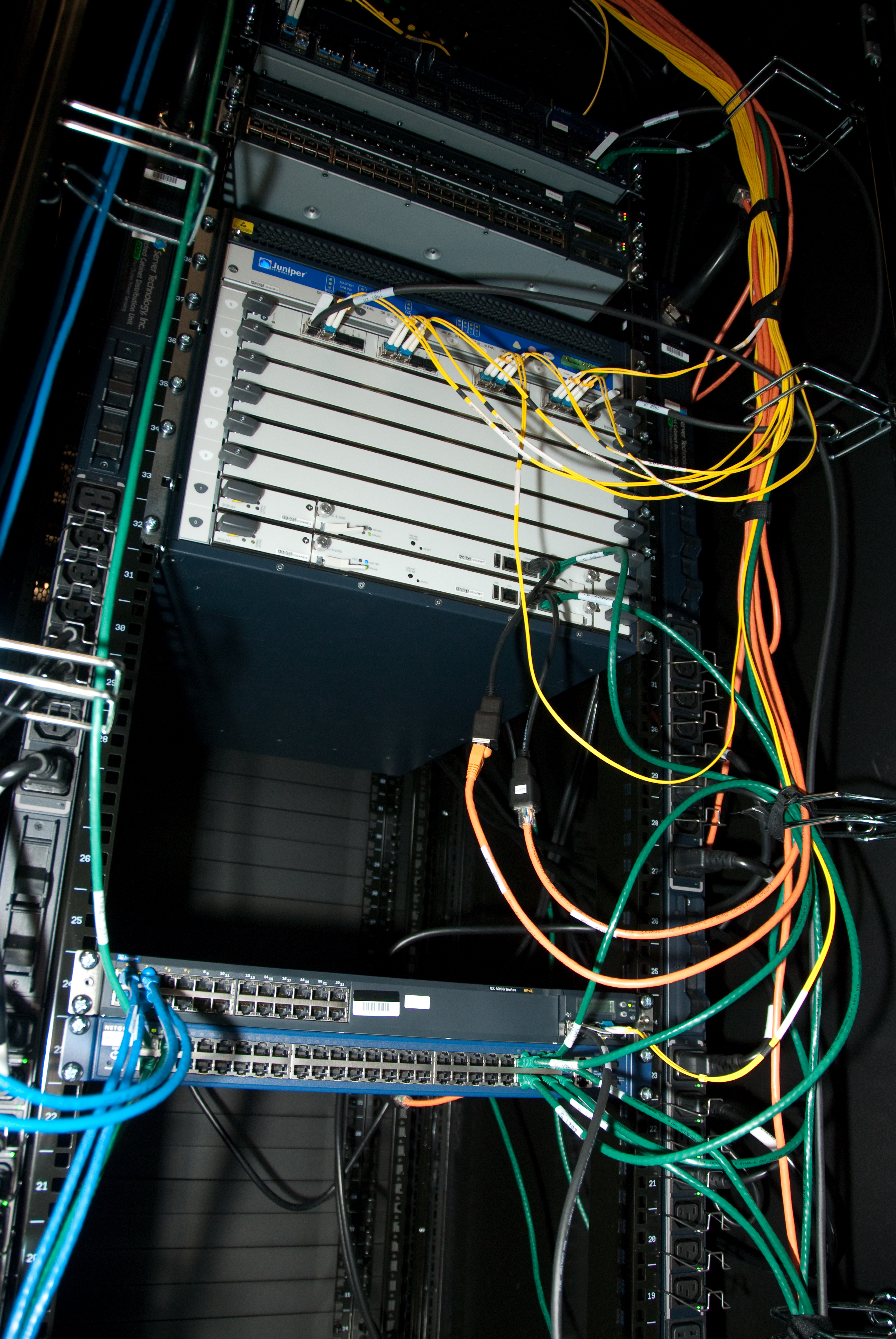
The foundational building blocks of a network—routers, switches, and firewalls—can be deployed in two fundamentally different ways.
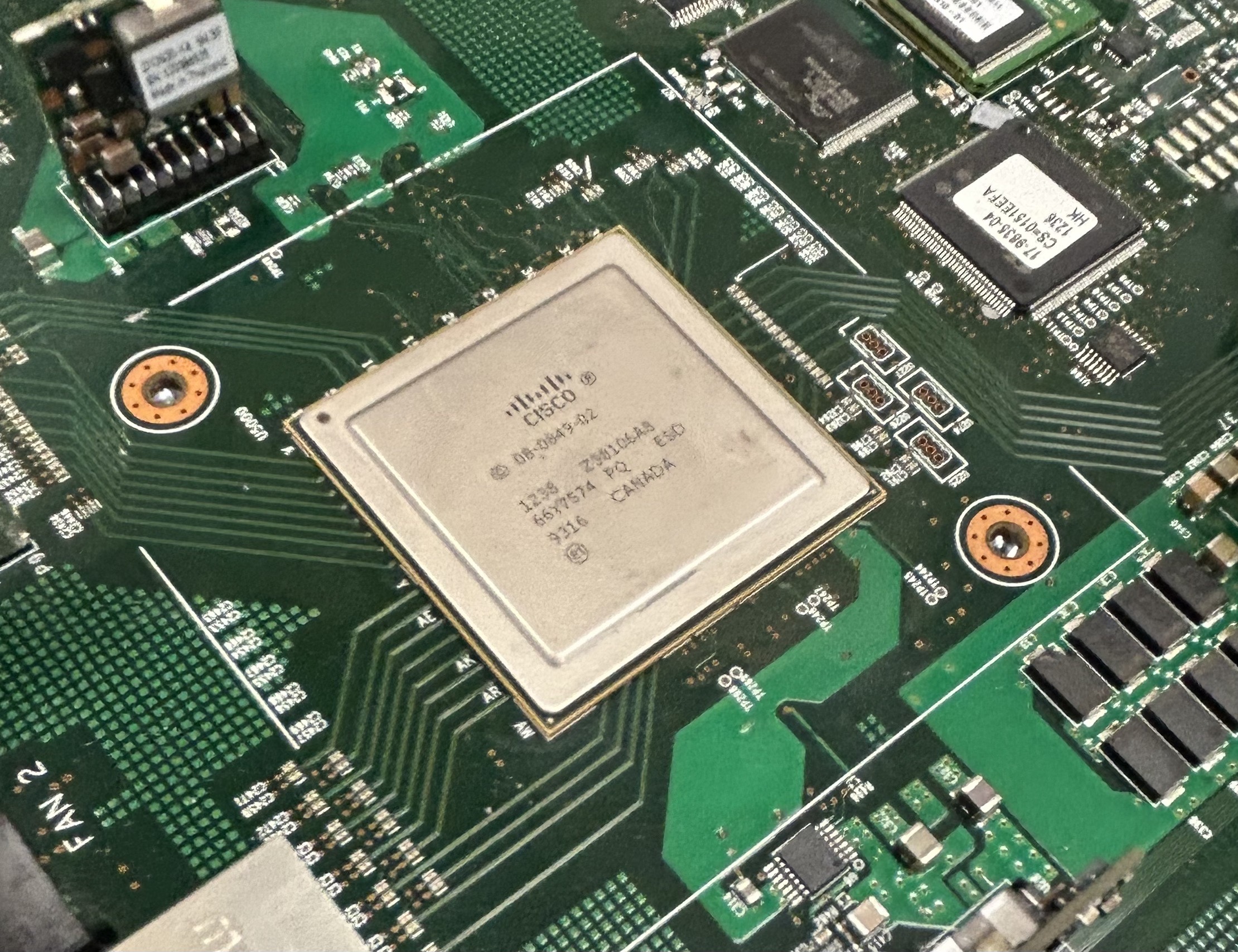
A physical network appliance is a dedicated hardware device engineered to perform specific networking functions. When you unpack a physical switch or firewall, you are handling a machine built for one job. Because these devices rely on dedicated Application-Specific Integrated Circuits (ASICs)—custom silicon chips hardwired to process packets—physical network appliances typically offer higher maximum throughput than virtual appliances.
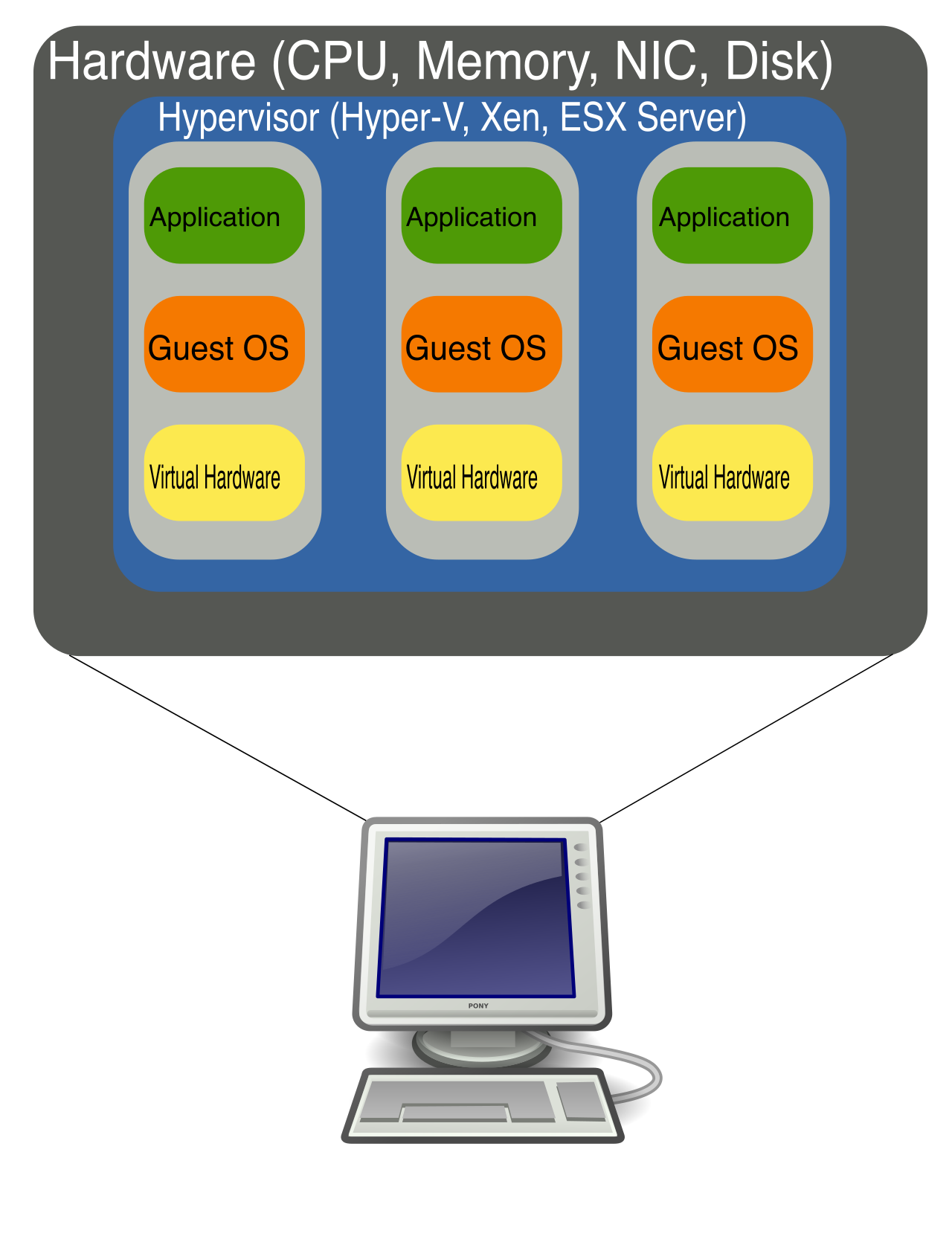
By contrast, a virtual network appliance is a software image operating within a hypervisor or container environment. Virtual network appliances provide equivalent networking functions to their physical hardware counterparts, but they eliminate the need for physical space, cabling, and dedicated power supplies. The primary advantage here is agility: virtual network appliances offer faster deployment times compared to physically installing hardware appliances. You can spin up a new virtual firewall in seconds rather than waiting weeks for a physical shipment.
The industry refers to this architectural shift as Network Functions Virtualization (NFV), a paradigm that replaces physical hardware appliances with virtual machine equivalents.
To understand how this changes a network administrator's daily reality, consider the evolution of the big three appliances:
| Appliance Type | The Physical Reality | The Virtual Equivalent |
|---|---|---|
| Router | A physical router uses dedicated hardware to forward packets between different physical IP networks. It sits in a rack connecting discrete office floors or buildings. | A virtual router is a software instance that performs packet forwarding between virtual networks within a virtualization host, allowing isolated virtual machines to route traffic locally. |
| Switch | A physical switch uses specialized hardware chips to forward Ethernet frames between physical devices at high speeds across twisted-pair cables. | A virtual switch is a software construct that forwards Ethernet frames between virtual machines residing on the same physical host server. |
| Firewall | A physical firewall is a standalone hardware appliance placed at the network perimeter to filter incoming and outgoing traffic between the LAN and the public internet. | A virtual firewall is a software-based security appliance deployed to filter traffic moving laterally between virtual machines within a data center (often called "East-West" traffic). |
As network applications scale, relying on a single server to handle all client requests becomes an architectural vulnerability.
The Load Balancer
A load balancer distributes incoming client requests across a pool of backend servers. This serves two immediate purposes. First, distributing traffic via load balancers prevents individual servers from becoming overwhelmed by high request volumes. Second, load balancers improve application availability by automatically redirecting traffic away from failed backend servers, ensuring the end-user experiences zero downtime.
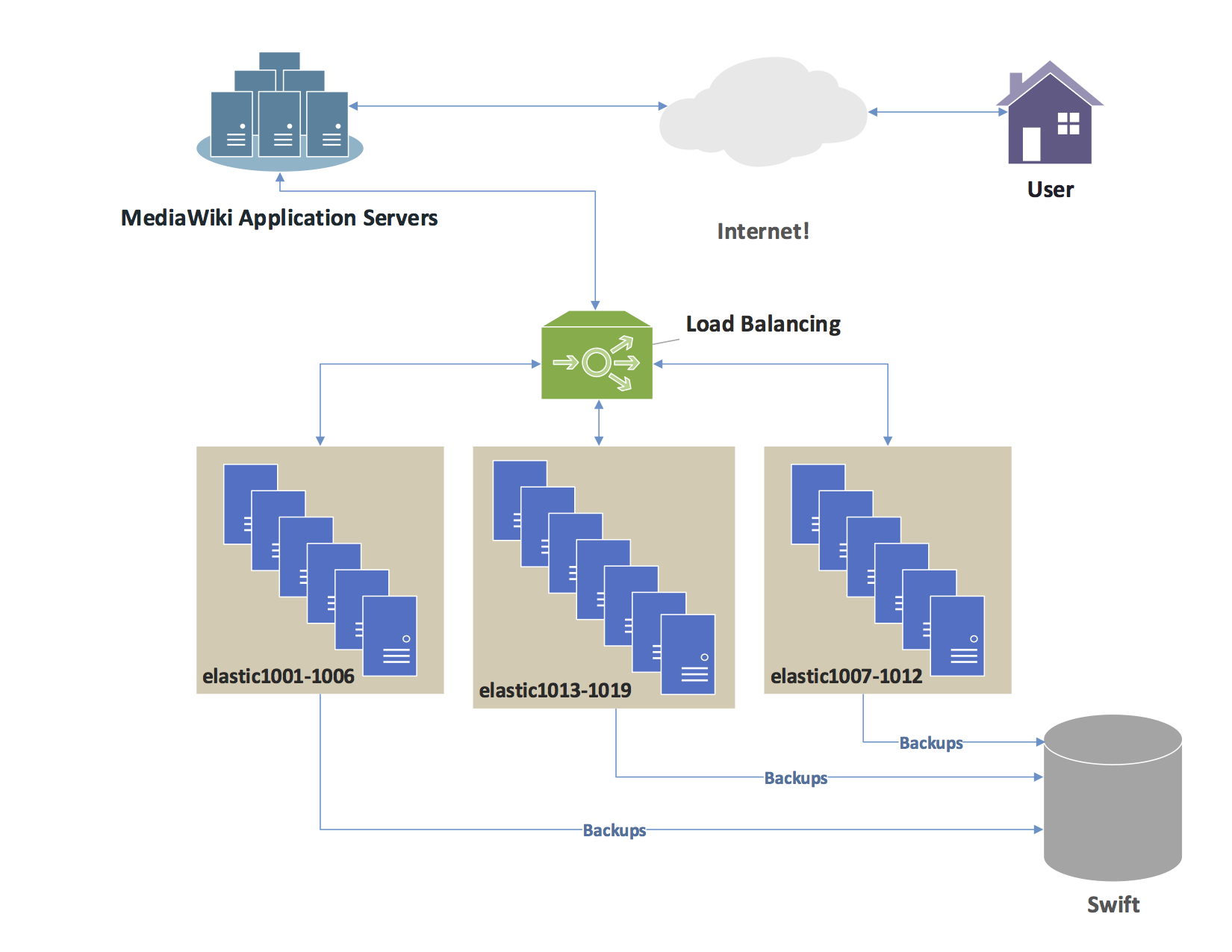
Load balancers operate at different layers of the OSI model, dictating how intelligently they can route traffic:
- Layer 4 Load Balancer: Makes routing decisions based strictly on IP addresses and transport layer port numbers (e.g., TCP port 443). It does not look at the actual contents of the packet.
- Layer 7 Load Balancer: Makes routing decisions based on application-level data such as HTTP headers or URL paths. It can route requests for
/imagesto one server pool and/videoto another.
To distribute this traffic, load balancers use specific mathematical algorithms. The simplest and most common is round-robin, a load balancing algorithm that distributes incoming requests sequentially across a pool of servers (Server 1, then Server 2, then Server 3, and repeat).
To ensure the load balancers themselves do not become single points of failure, network architects deploy them in high-availability clusters:
- Active-active load balancing maintains multiple active instances simultaneously processing network traffic, maximizing throughput.
- Active-passive load balancing keeps a secondary node in standby mode until the primary node fails, whereupon it instantly takes over routing duties.
The Proxy Server
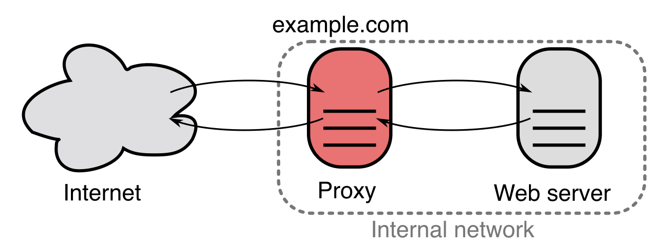
While a load balancer distributes traffic among your servers, a proxy server acts as an intermediary routing agent between a client application and an external server. Proxies face either inward or outward, and their directionality defines their function.
Forward Proxies Forward proxies intercept outbound client requests before the requests reach the public internet. When a user in your office attempts to visit a website, the forward proxy fetches the site on their behalf.
- Anonymity: Forward proxies hide internal client IP addresses from external web servers.
- Efficiency: Forward proxies cache frequently accessed web content to reduce external bandwidth consumption. If fifty employees read the same news article, the proxy downloads it once and serves it locally fifty times.
- Security: Forward proxies can filter outbound web requests to block access to unauthorized websites based on corporate policies.
Reverse Proxies Reverse proxies intercept inbound internet requests before the requests reach internal backend servers. When an external customer visits your company's web application, they are actually talking to your reverse proxy.
- Protection: Reverse proxies hide the identities and IP addresses of internal backend servers from external clients, making it much harder for attackers to map your internal network.
- Performance: Reverse proxies frequently provide SSL/TLS encryption offloading to reduce the processing burden on backend web servers. The proxy handles the computationally heavy math of encrypting and decrypting data, allowing the web servers to focus entirely on serving application logic.
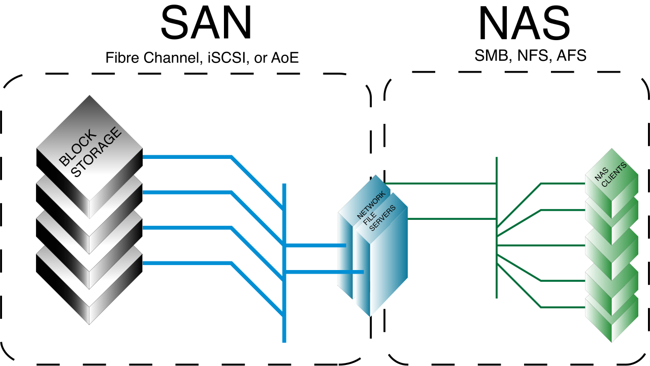
Modern networks must rapidly transport immense volumes of data. However, not all network storage is created equal. The distinction between a Storage Area Network (SAN) and Network Attached Storage (NAS) dictates how servers read and write their data.
Storage Area Network (SAN) A Storage Area Network provides block-level data storage access over a specialized high-speed network.
To the connected client server, SAN block-level storage appears as a local raw hard drive. The operating system formats it, partitions it, and treats it exactly as if the drive were physically bolted inside the chassis. Because of this deep integration, Storage Area Networks frequently utilize the Fibre Channel protocol for high-speed data transmission across dedicated optical networks. Alternatively, to save costs, Storage Area Networks frequently utilize the iSCSI protocol to transmit block storage commands over standard IP networks.
Network Attached Storage (NAS) Network Attached Storage provides file-level data storage access over a standard Ethernet network.
To the connected client systems, Network Attached Storage file-level storage appears as a shared network folder (e.g., a mapped "Z: Drive"). The NAS appliance handles its own file system. To facilitate this sharing, Network Attached Storage devices frequently utilize the Server Message Block (SMB) protocol for file sharing in Windows environments, and the Network File System (NFS) protocol for file sharing in Linux environments.
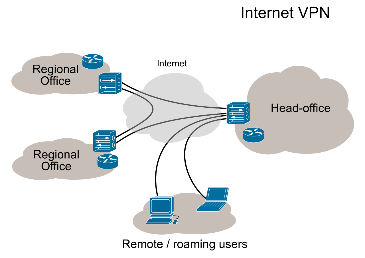
When data must traverse the public internet, it relies on cryptographic tunnels. A Virtual Private Network (VPN) creates a secure encrypted connection over an untrusted network like the internet. By doing so, Virtual Private Networks ensure data confidentiality by encrypting packets transmitted across public networks, rendering them mathematically unreadable to eavesdroppers.
We categorize VPNs by the endpoints they connect:
Site-to-Site VPNs
A site-to-site Virtual Private Network connects two distinct local area networks together over the internet, seamlessly bridging a corporate headquarters with a remote branch office. To achieve this, site-to-site Virtual Private Networks typically utilize IPsec protocols to establish permanent secure tunnels between remote branch routers. The users in either building simply access resources as if they were on the same physical LAN, largely unaware the VPN even exists.
Client-to-Site VPNs
A client-to-site Virtual Private Network connects an individual remote user's device directly to a corporate network. If you are working from a coffee shop, you use a client-to-site VPN to access internal company servers.
When configuring a client VPN, network administrators face a crucial routing decision:
- Full tunneling is a configuration that forces all network traffic from the client device through the encrypted Virtual Private Network connection. This maximizes security but consumes vast amounts of corporate bandwidth.
- Split tunneling is a configuration that routes corporate traffic through the Virtual Private Network while sending general internet traffic directly out the local gateway. If a user accesses an internal database, the traffic is encrypted; if they stream a video on YouTube, the traffic uses the coffee shop's public internet.
To handle the cryptographic overhead of thousands of remote workers, enterprises deploy a VPN concentrator, a dedicated appliance engineered specifically to manage numerous simultaneous Virtual Private Network tunnels.
Not all network traffic carries equal importance. A delayed email is an annoyance; a delayed voice packet destroys a phone call.
Quality of Service (QoS) is a set of technologies that manage network resources to prioritize specific types of traffic. Fundamentally, Quality of Service mechanisms guarantee minimum bandwidth for critical network applications during periods of high network congestion.
To understand QoS, we must understand the twin enemies of real-time communication:
- Latency: The time delay required for a data packet to travel from its source to its destination.
- Jitter: The variation in latency between received data packets in a network stream.
Voice over IP (VoIP) traffic requires high Quality of Service prioritization due to its extreme sensitivity to network delays. High jitter causes choppy audio in real-time communication applications, rendering voice calls unintelligible.
To enforce this prioritization, network devices look at the Differentiated Services Code Point (DSCP), a field in an IP packet header used to classify traffic for Quality of Service prioritization. Think of DSCP as a VIP ticket printed directly on the packet.
When congestion occurs, routers and switches utilize two primary traffic conditioning mechanisms:
- Traffic shaping is a Quality of Service mechanism that buffers and delays certain traffic to ensure a steady flow of high-priority packets. It smooths out traffic bursts by holding non-critical packets in memory temporarily.
- Traffic policing is a Quality of Service mechanism that immediately drops network packets exceeding a configured maximum bandwidth rate. It is a hard limit; cross the threshold, and the packet is destroyed.
Even with perfect internal networks, delivering an application globally introduces unavoidable geographic latency. You cannot out-engineer the speed of light. If your web server is in New York, a user in Tokyo will inherently experience a delay when loading your site.
The solution is a Content Delivery Network (CDN), a geographically distributed group of servers designed to cache static web content. Content Delivery Networks routinely cache static assets like images, stylesheets, and JavaScript files.
By pushing these assets to the "edge" of the internet, Content Delivery Networks reduce webpage load times by serving requests from the server geographically closest to the end user. When the Tokyo user requests an image, they download it from a CDN server in Tokyo, not the origin server in New York.
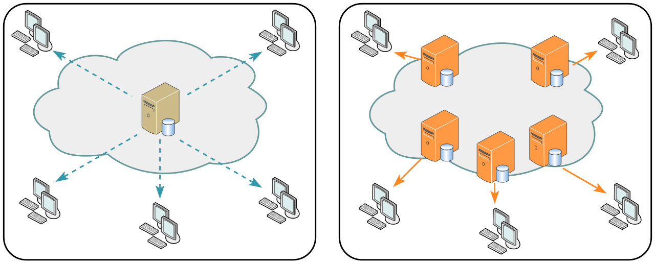
This architecture provides two massive operational benefits:
- Bandwidth Reduction: Content Delivery Networks decrease the total bandwidth load on the origin web server by delivering cached static assets directly to clients. The origin server only has to generate dynamic database queries.
- Security Integration: Content Delivery Networks provide protection against Distributed Denial of Service (DDoS) attacks by absorbing malicious traffic across their massive distributed infrastructure. Because the CDN's capacity is orders of magnitude larger than any single enterprise network, it can simply ingest and filter an attack without breaking a sweat.