Troubleshooting Performance Issues
Not sure you’re ready?
Take the ~3-minute readiness diagnostic and see where you stand.
Picture a highly pressurized volume of water flowing through a massive municipal aqueduct, suddenly forced into a half-inch garden hose. The immediate backlog, localized pressure spikes, and inevitable overflow perfectly illustrate the physical realities of data transmission across modern networks. A network is not an infinite void; it is a meticulously engineered system of finite mathematical capacities and physical limitations. When the demands of users and applications collide with these physical boundaries, the result is performance degradation. Mastering network troubleshooting requires moving beyond simply replacing cables to diagnosing the exact points where data physics breaks down—whether that manifests as overflowing hardware buffers in a datacenter switch or the chaotic collision of electromagnetic waves in a corporate office.
To diagnose a slow or failing network, we must first understand how traffic behaves when pushed to its physical limits.
Network congestion occurs when the volume of network traffic exceeds the bandwidth capacity of the network infrastructure. Think of this as putting ten thousand cars on a two-lane highway. But congestion rarely happens uniformly across an entire topology. Instead, it concentrates at a bottleneck, a specific point in a network where data flow is restricted due to limited capacity or processing power.
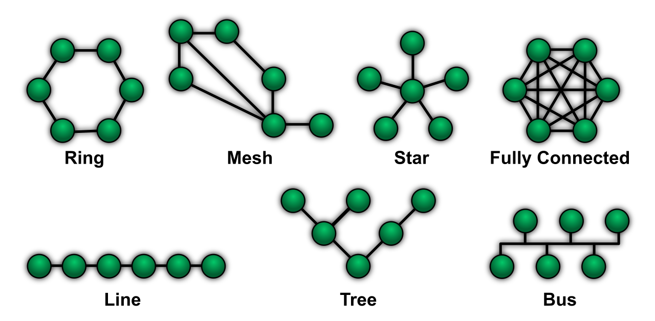
Real-World Observation: Network bottlenecks frequently manifest when high-speed network uplinks connect directly to lower-speed network interfaces. For instance, aggregating multiple 10 Gbps switch ports into a single 1 Gbps router uplink creates an immediate mathematical bottleneck.
When traffic at this bottleneck reaches its absolute limit, we achieve bandwidth saturation, which occurs when a network link operates at 100% of its available data transmission capacity.
The TCP Feedback Loop of Doom
What happens to the next packet of data that arrives at a completely saturated link? Physics and device logic offer only one solution: a completely saturated network link will natively drop any new incoming packets attempting to traverse that specific link.
This introduces packet loss, which occurs when one or more data packets fail to reach the intended destination address across a computer network. Congested network links are a primary cause of packet loss because network devices drop incoming packets when their processing buffers are full.
This is where the network's own reliability mechanisms betray it. Transmission Control Protocol (TCP) guarantees data delivery. If an application is streaming a file and packets are dropped at a congested router buffer, the receiving device never acknowledges them. High packet loss on a network typically triggers TCP retransmissions. The sender simply resends the missing data.
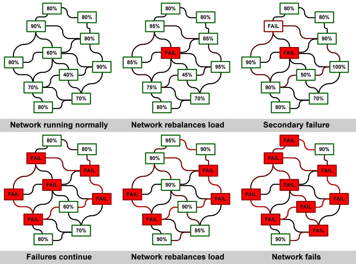
However, because the link is already overflowing, TCP retransmissions further contribute to network congestion by adding duplicate packets to the network load. This creates a cascading failure: congestion causes drops, drops cause retransmissions, and retransmissions cause more congestion.
Latency, Jitter, and Asymmetrical Routing
When traffic is delayed but not dropped, we measure the impact in time. Latency is the total time required for a data packet to travel from the source node to the destination node. To diagnose this, technicians rely on the ping command-line tool, which measures network latency by calculating the round-trip time of ICMP Echo Request packets.
Sometimes, latency is not caused by traffic volume, but by geography and routing logic. Asymmetrical routing introduces performance issues and erratic latency when return network traffic takes a fundamentally different and slower path than the outbound traffic.
While raw latency is frustrating, inconsistency is fatal to modern applications. Jitter is the variation in the latency of received data packets over a given time period. Imagine a commute to work: if it takes exactly 30 minutes every day (high latency), you can plan for it. If it takes 10 minutes on Monday, 90 minutes on Tuesday, and 5 minutes on Wednesday (high jitter), your schedule is ruined.
Real-time network applications like Voice over IP (VoIP) and video conferencing are highly sensitive to high jitter levels. Because voice packets must be played back in a smooth, continuous stream, chaotic arrival times result in robotic, clipped, or overlapping audio.
To mitigate this, endpoints employ a jitter buffer, which mitigates the effects of network jitter by temporarily storing arriving packets and outputting them to the application at a constant rate.
Imposing Order: QoS and Traffic Shaping
Since we cannot always purchase infinite bandwidth to solve congestion, we must govern the traffic.
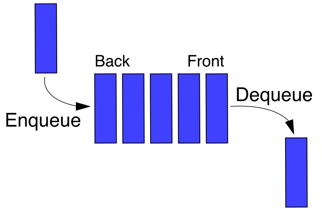
- Quality of Service (QoS) prioritizes specific types of network traffic to mitigate the effects of network congestion. By reading packet headers, a switch can ensure that sensitive VoIP packets are placed at the front of the queue, while bulk file transfers are forced to wait.
- Traffic shaping is a bandwidth management technique that delays certain packets to ensure higher-priority traffic flows smoothly. Rather than hard-dropping low-priority traffic, shaping queues it up, artificially slowing it down to prevent it from saturating the link.
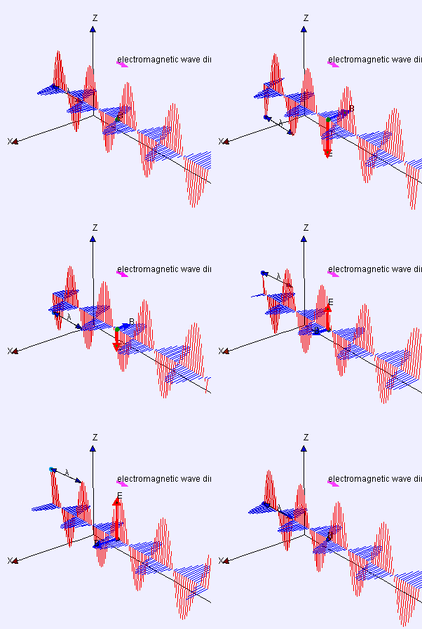
When we transition from copper and fiber optics to the airwaves, the physics of troubleshooting shift dramatically. Data is no longer bound by a physical jacket; it is broadcast as electromagnetic radiation.
Attenuation and Signal Strength
Signal attenuation is the natural reduction in wireless signal strength as the electromagnetic waves travel away from the transmission source. Even in a vacuum, a signal weakens over distance (the inverse-square law). In a typical office environment, physical obstacles like concrete walls and metal doors cause high levels of wireless signal attenuation.
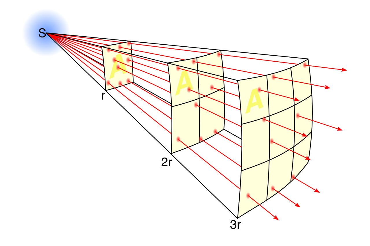
To diagnose wireless health, we measure the Received Signal Strength Indicator (RSSI), which measures the power level of a wireless signal received by a specific client device.
Understanding RSSI: Received Signal Strength Indicator (RSSI) values are typically represented as negative numbers measured in decibels relative to a milliwatt (dBm). Because they are negative, a Received Signal Strength Indicator (RSSI) value closer to zero indicates a stronger and more robust wireless signal. An RSSI of -40 dBm is excellent, whereas -85 dBm is dangerously weak.
A strong signal is useless if the environment is too "loud." The Signal-to-Noise Ratio (SNR) mathematically compares the level of a desired wireless signal to the level of background electromagnetic noise. A higher Signal-to-Noise Ratio (SNR) value indicates a cleaner and more reliable wireless network connection.
The Origins of Wireless Noise
Background noise and interference come in two primary forms: Environmental and Electomagnetic.
Electromagnetic Interference (EMI) disrupts wireless signals through electromagnetic radiation emitted from external electrical sources. The ubiquitous 2.4 GHz frequency band is particularly vulnerable to everyday office and household items. Microwave ovens operate in the 2.4 GHz frequency band and frequently cause Electromagnetic Interference (EMI) for nearby Wi-Fi networks. Similarly, cordless phones and legacy Bluetooth devices often cause localized interference in the 2.4 GHz wireless frequency band.
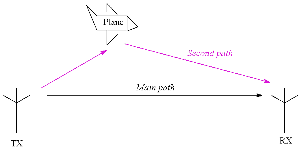
Sometimes the interference is not an external emitter, but the Wi-Fi signal itself bouncing around the room. Multipath interference occurs when a single wireless signal bounces off obstacles and arrives at the receiving antenna via multiple paths at slightly different times. This echo-like effect confuses the receiver. In warehouses and server rooms, environmental factors like large metal shelving units cause multipath interference by heavily reflecting wireless signals.
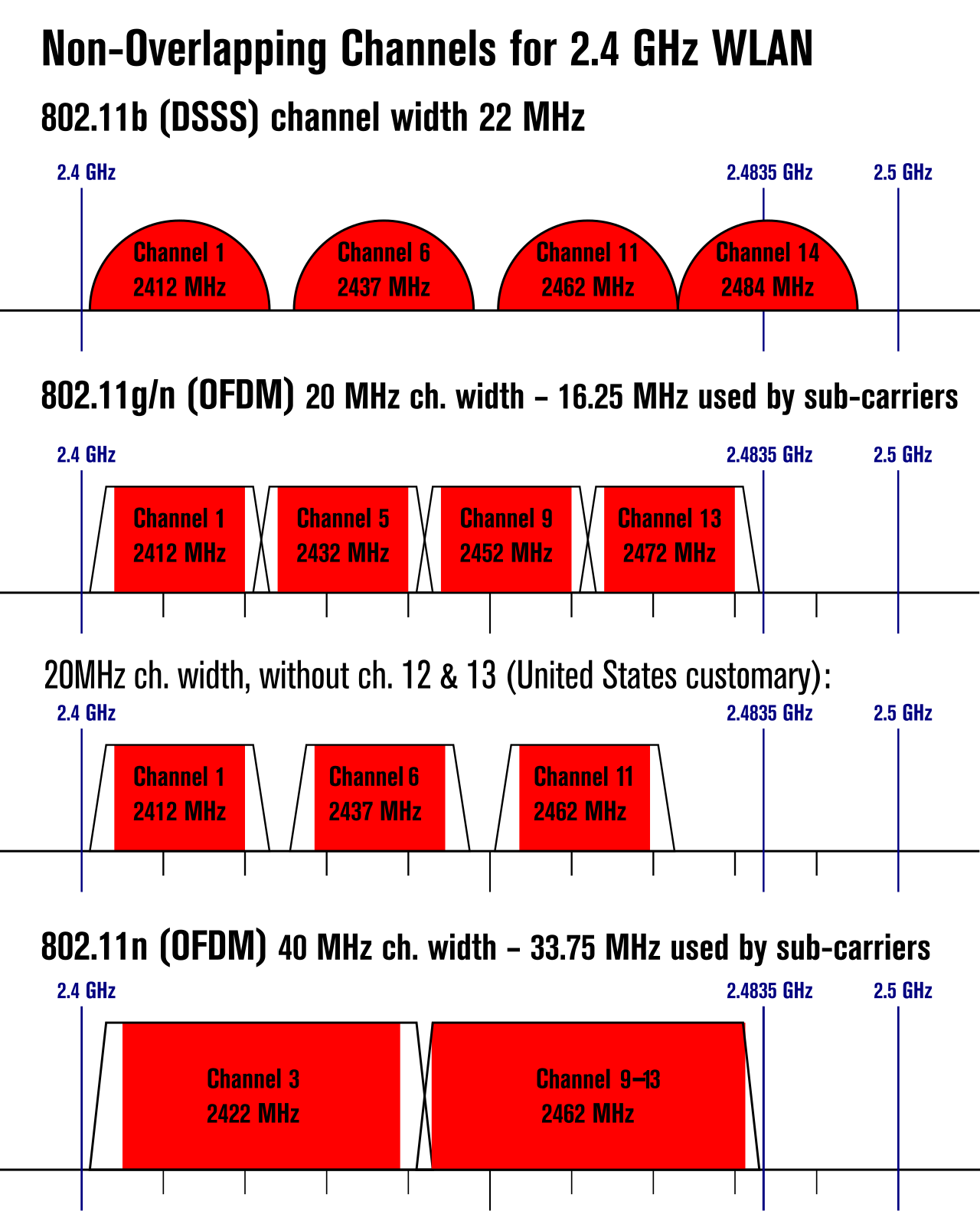
Because wireless is a shared medium, Access Points (APs) must carefully divide the available frequency into "channels" to avoid talking over one another. Mismanaging these channels is a leading cause of degraded wireless performance.
| Interference Type | Definition |
|---|---|
| Co-channel interference | Occurs when multiple nearby wireless access points are configured to use the exact same frequency channel, forcing them to take turns transmitting. |
| Adjacent-channel interference | Occurs when overlapping frequency bands from nearby wireless channels bleed into and interfere with each other, causing data corruption. |
To avoid these collisions, we must rely on non-overlapping channels.
- The 2.4 GHz Band: The 2.4 GHz Wi-Fi frequency band provides a total of only three non-overlapping channels. Due to this mathematical limitation, Channels 1, 6, and 11 are the standard non-overlapping channels utilized in the North American 2.4 GHz Wi-Fi band.
- The 5 GHz Band: By contrast, the 5 GHz Wi-Fi band provides significantly more non-overlapping channels compared to the 2.4 GHz Wi-Fi band, allowing for much denser AP deployments.
However, the 5 GHz band shares airspace with radar systems. To comply with federal regulations, enterprise APs utilize Dynamic Frequency Selection (DFS), which automatically changes the wireless access point channel to avoid interfering with military or weather radar systems operating in the 5 GHz band.

The ultimate promise of enterprise Wi-Fi is mobility. Users expect to walk from the lobby to the boardroom on a VoIP call without dropping the connection.
Wireless roaming is the process of a client device seamlessly moving its network connection from one access point to another without dropping the active session. For this to work, the infrastructure must be perfectly synchronized. Wireless access points must broadcast the exact same Service Set Identifier (SSID) to support seamless wireless client roaming. Furthermore, wireless access points must utilize identical security protocols and passwords to allow seamless client roaming across the network.
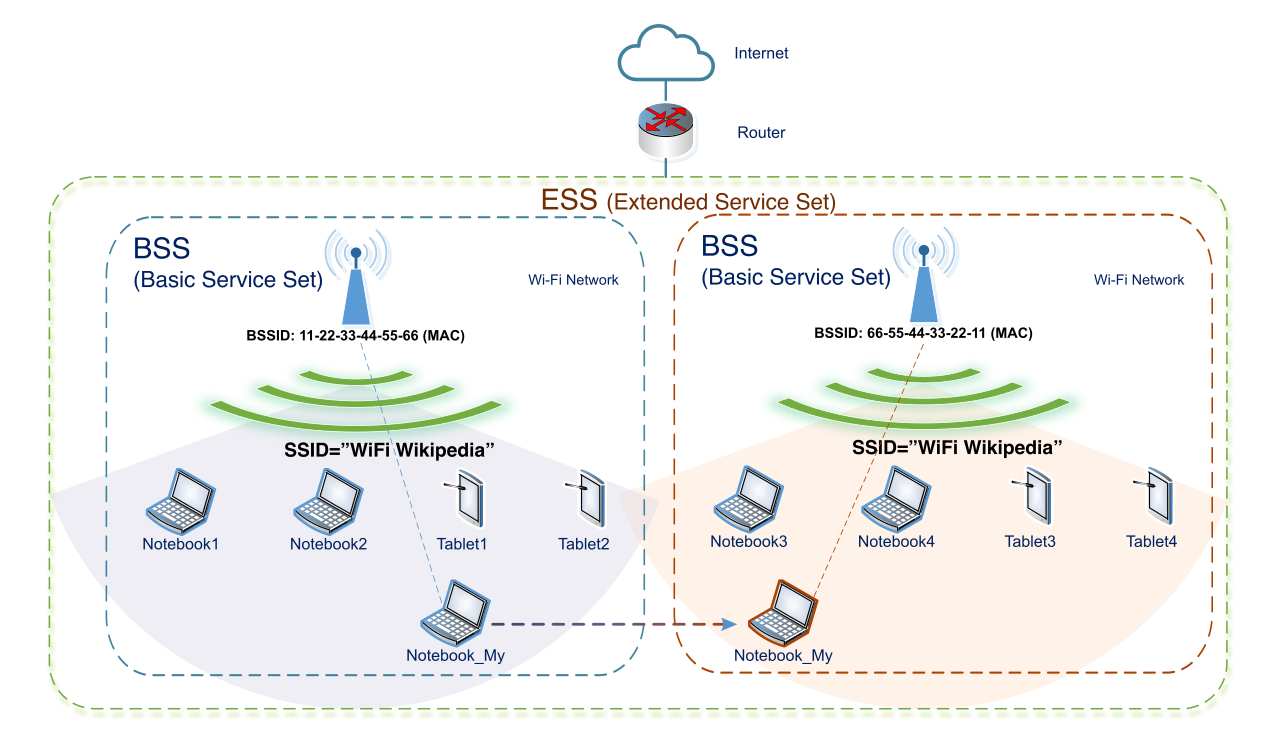
If these configurations differ, the transition fails. Client disassociation occurs when a wireless device formally disconnects or is forcibly disconnected from a wireless access point. For example, mismatched security credentials will cause a wireless access point to immediately reject and disassociate a connecting client device.
The Sticky Client Problem
Even with perfect SSID and security matching, clients often make poor roaming decisions. Client devices, not the access points, ultimately decide when to roam.
A roaming misconfiguration occurs when a client device remains connected to a distant access point with a weak signal instead of transitioning to a closer access point with a stronger signal. The phenomenon of a wireless client inappropriately clinging to a distant access point with a degraded signal is commonly called the sticky client problem.
Sticky clients drag down the performance of the entire wireless cell because their degraded, slow communication consumes disproportionate amounts of broadcast time.
Forcing the Handoff: Tuning Power and Data Rates
To resolve sticky clients and optimize roaming, network administrators must carefully tune the physical broadcast environment.
First, access point transmit power must be properly tuned to create optimal cell overlap areas for successful client roaming. This is a delicate balancing act:
- Excessive wireless cell overlap from overly high access point transmit power causes confusion and delays during client roaming, as the client device sees too many equally viable APs and struggles to choose.
- Conversely, insufficient wireless cell overlap from excessively low access point transmit power creates dead zones and causes dropped connections during client roaming.
If tuning the transmit power fails to cure a sticky client, we can alter the AP's rules of engagement. Raising the minimum basic data rate on an access point forces clients with weak signals to disconnect sooner and roam to a closer access point. By disabling the lowest, slowest transmission speeds (such as 1 Mbps or 2 Mbps), the AP essentially tells the distant client: "If you cannot speak clearly and quickly, I will not listen to you." The client is then forced to disassociate and seek out the louder, closer AP, restoring harmony and performance to the network.