Switching Technologies and Features
Not sure you’re ready?
Take the ~3-minute readiness diagnostic and see where you stand.
Imagine a massive corporate office lacking internal walls, where thousands of employees shout simultaneously to communicate. Every request, every page for a colleague, and every piece of trivial gossip echoes across the open floor, consuming everyone’s attention. A standard Ethernet network operates precisely this way out of the box. Without logical segmentation, every connected device shares a single broadcast domain. Whenever a machine sends an Address Resolution Protocol (ARP) broadcast, every other machine’s processor must pause to evaluate it. The modern enterprise switch is the architectural solution to this noise, allowing network engineers to erect invisible, soundproof walls through advanced switching technologies and virtual boundaries.
To control the chaos of an open network, a Virtual Local Area Network (VLAN) creates a separate broadcast domain on a Layer 2 switch. By carving the physical switch into distinct logical partitions, we contain the noise. Out of the box, however, no walls exist. The default VLAN on a standard enterprise switch is VLAN 1, meaning all interfaces initially belong to the same unified broadcast domain.
The switch achieves this isolation mathematically. At its core, a switch MAC address table maps hardware MAC addresses to specific switch ports and VLAN identifiers. When you configure the switch, assigning a port to a specific VLAN isolates the port traffic from other VLANs on the same switch.
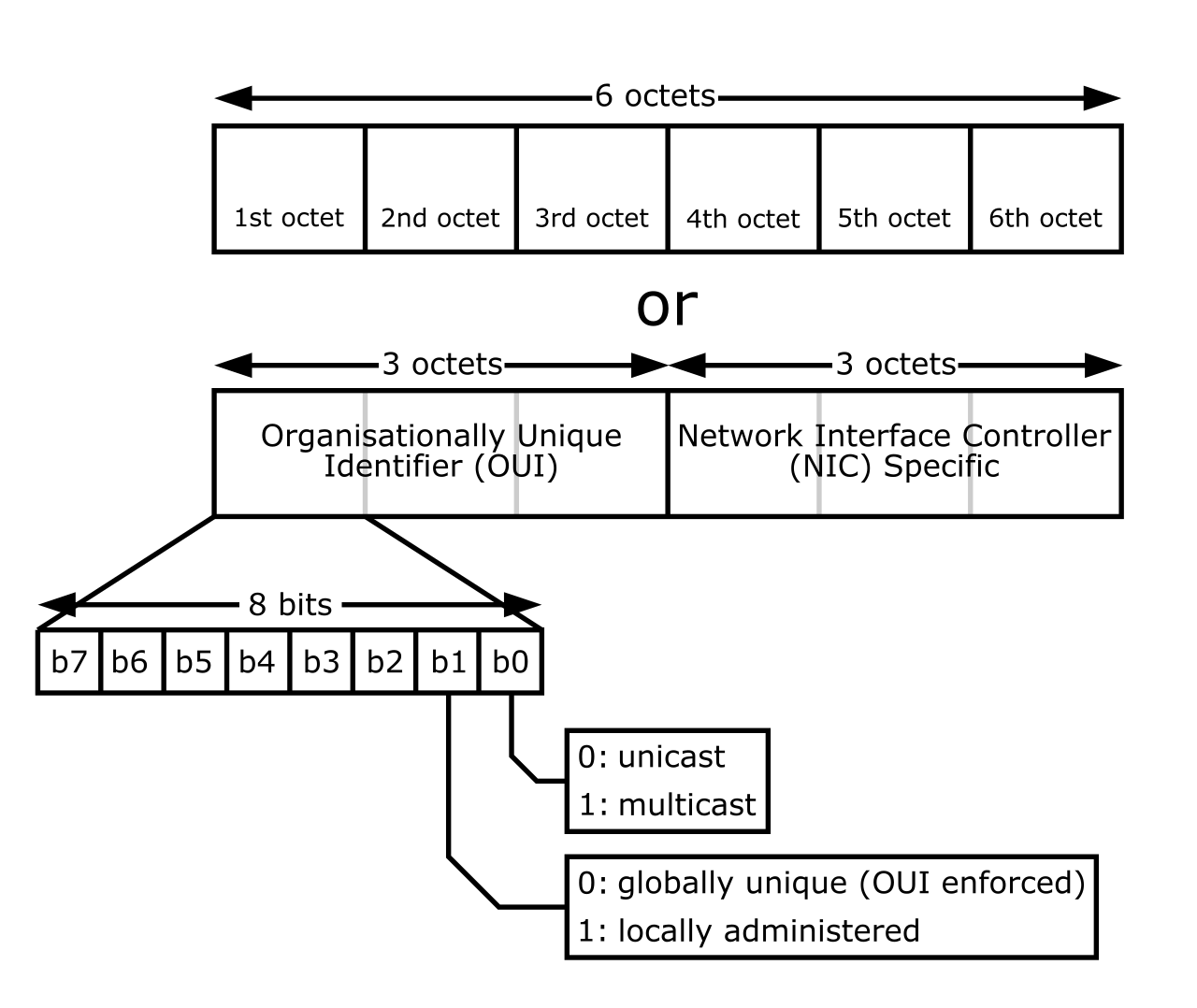
For the standard user—say, an accountant with a desktop PC—the network connection must appear seamless. Their machine connects to an access port, which is an interface configured so that an access port carries network traffic for only a single VLAN. The desktop remains blissfully unaware that it belongs to "VLAN 20"; the switch strips away any complexity, forwarding traffic strictly within that designated domain.
We encounter an immediate problem once we isolate our network: security and order are achieved, but now the accountants in VLAN 20 cannot talk to the servers in VLAN 50. Because Layer 2 isolation is absolute, inter-VLAN routing is required to forward traffic between different Virtual Local Area Networks.
Historically, this meant running a physical cable from the switch to an external router—a topology known as "router on a stick." Today, we handle this entirely within the silicon of the switch itself using virtual interfaces. A Switch Virtual Interface (SVI) acts as a default gateway for hosts residing in a specific VLAN. Rather than leaving the chassis, traffic hits the SVI, gets routed, and drops directly into the destination VLAN. Fundamentally, Switch Virtual Interfaces enable Layer 3 routing capabilities on a Layer 3 switch, allowing high-speed internal routing at wire speeds.
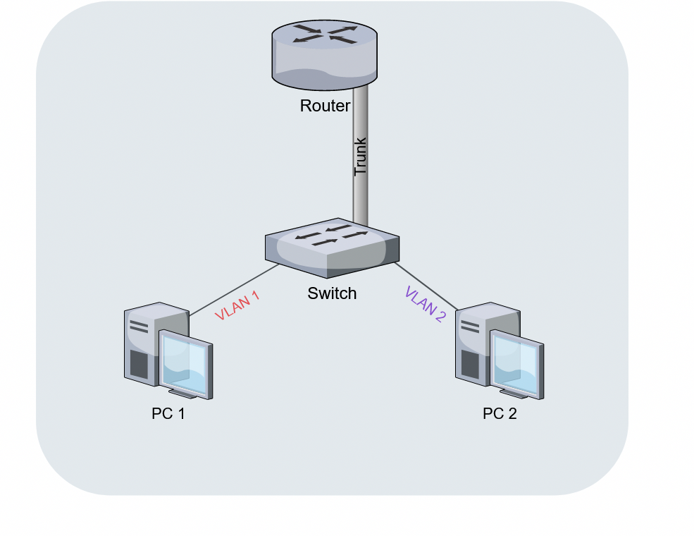
Consider a scenario where you have 40 distinct VLANs spanning across an entire campus, but only a single fiber optic cable linking two switches together. You cannot map 40 VLANs to 40 physical cables. Instead, you use a trunk. A trunk port carries network traffic for multiple VLANs across a single physical link.
But how does the receiving switch know which frame belongs to the accounting VLAN and which belongs to the server VLAN as they travel down the same wire? It requires an explicit label.
The IEEE 802.1Q standard defines VLAN tagging for Ethernet frames.
When a frame traverses a trunk, an 802.1Q tag inserts a four-byte field into the original Ethernet frame header. Within those four bytes lies the critical payload: the 802.1Q tag contains a twelve-bit VLAN Identifier to specify the associated VLAN for a frame. The math here governs our network sizing. Because the identifier is 12 bits long (212=4096), a twelve-bit VLAN Identifier field supports up to 4,094 distinct VLANs (reserving 0 and 4095 for system use).
While network engineers usually configure trunk ports manually, switches can negotiate these links automatically. Dynamic Trunking Protocol (DTP) is a proprietary protocol used to negotiate trunking on a link, allowing switches to dynamically agree to form a trunk connection when plugged into one another.
Native and Voice VLANs
Not all traffic traversing a trunk carries a tag. A native VLAN carries untagged traffic over an 802.1Q trunk link. If a switch receives a normal, untagged Ethernet frame on a trunk port, it assumes that frame belongs to the native VLAN.
This creates a serious vulnerability if poorly configured. Mismatched native VLANs between two connected switches cause traffic leakage between those VLANs, essentially bleeding data from one secured segment into another. Worse yet, because spanning tree protocols rely on predictable topologies, mismatched native VLANs between two connected switches cause spanning tree bridging loops, which can instantly collapse an enterprise network.
Trunks and tags aren't limited to switch-to-switch connections. Look closely at a typical corporate desk: a PC often plugs directly into the back of an IP phone, which in turn plugs into the wall. To ensure phone calls aren't interrupted by the PC downloading large files, a voice VLAN allows a switch port to prioritize IP phone traffic over standard data traffic. Because both devices share a single physical cable, voice VLANs require 802.1Q tagging to separate voice frames from data frames on a single physical port. The phone tags its own voice traffic, while passing the PC's untagged data traffic straight to the switch's access VLAN.
Network engineers demand high availability, which means installing redundant cables between switches. However, Ethernet does not have a "Time to Live" field for Layer 2 frames. If a loop is physically created, broadcast frames will circulate infinitely, multiplying exponentially until the switches' processors overload and the network melts down—a phenomenon known as a broadcast storm.
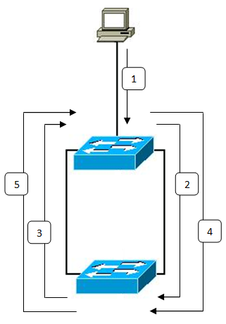
To prevent this, the IEEE 802.1D standard originally defined the Spanning Tree Protocol (STP). The primary purpose of the Spanning Tree Protocol is to prevent Layer 2 switching loops in a network. It maps the physical network, finds the loops, and breaks them logically. The Spanning Tree Protocol prevents network loops by placing redundant switch ports into a blocking state, holding them in reserve until a primary link fails.
The STP Election Process
STP relies on an election to determine the center of the network universe, known as the root bridge. The Spanning Tree Protocol elects a root bridge based on the lowest bridge ID.
A Spanning Tree Protocol bridge ID consists of a bridge priority value and the switch MAC address. To ensure predictable behavior, network engineers manipulate the priority. The default Spanning Tree Protocol bridge priority value is 32768. Because lower Spanning Tree Protocol bridge priority numbers indicate a higher preference to become the root bridge, an administrator can manually lower this value on their most powerful core switch, ensuring it wins the election.
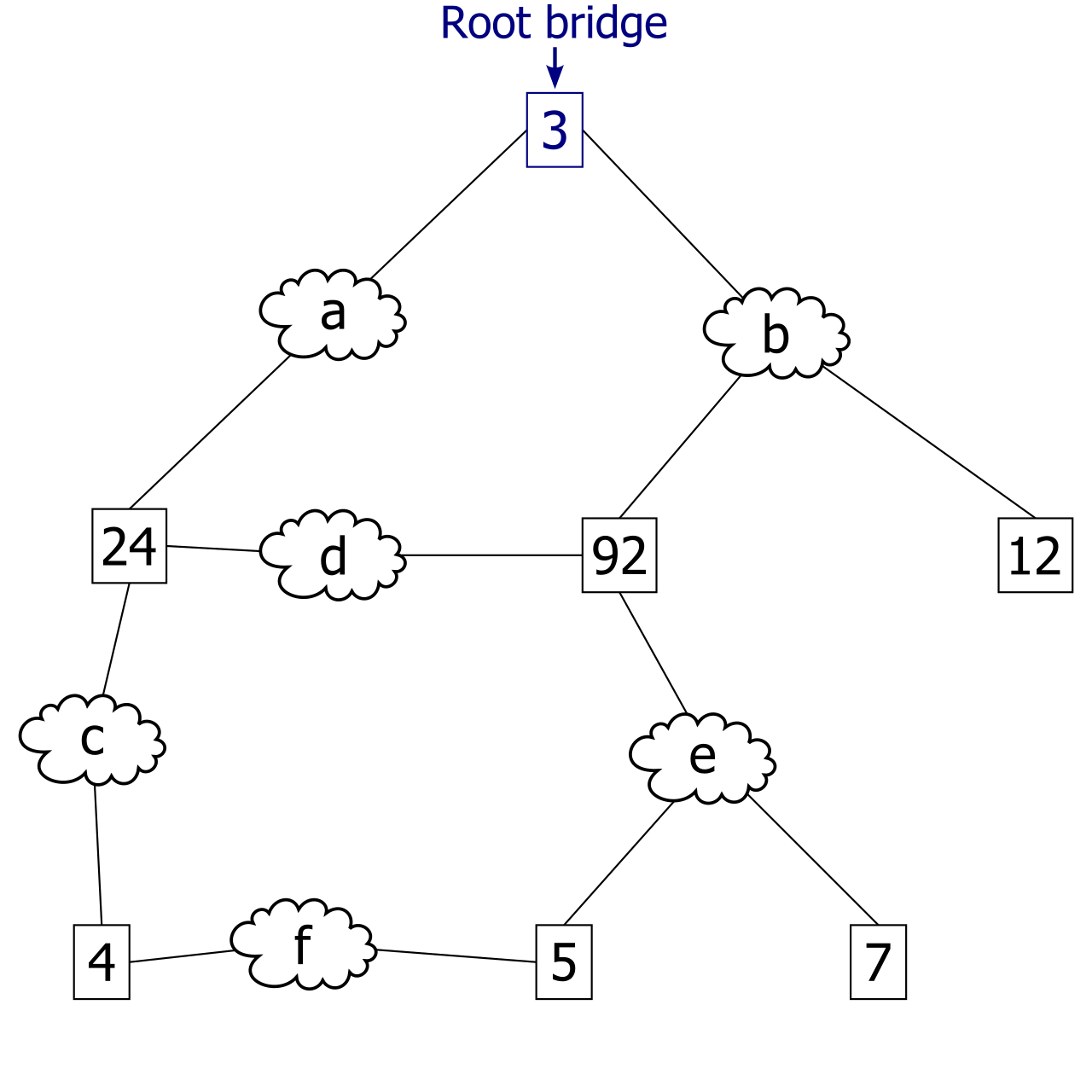
Once the root bridge is crowned, the remaining switches determine their shortest path to it.
- A Spanning Tree Protocol root port is the port on a non-root switch with the lowest path cost to the root bridge.
- A Spanning Tree Protocol designated port forwards traffic on a network segment toward the root bridge. Any redundant port that doesn't fit these essential roles is blocked.
Evolution and Protection
Original STP was slow, often taking up to 50 seconds to recalculate a path if a link went down. Today, Rapid Spanning Tree Protocol (RSTP) is defined by the IEEE 802.1w standard. Rapid Spanning Tree Protocol significantly reduces convergence time compared to legacy Spanning Tree Protocol, shifting the recovery window from agonizing seconds down to mere milliseconds.
Switches continually monitor the loop-free topology via heartbeat messages. Bridge Protocol Data Unit (BPDU) frames are used by switches to share spanning tree information. However, BPDUs are dangerous if an end-user plugs a rogue switch into an access port in a conference room, potentially triggering an unwanted STP election. To defend the perimeter, Bridge Protocol Data Unit Guard (BPDU Guard) disables a switch port if a Bridge Protocol Data Unit frame is received on that port, instantly quarantining the threat.
When a single gigabit uplink between switches becomes saturated, simply plugging in a second cable would invoke STP, which would promptly block the redundant link. To utilize both cables simultaneously, we must trick the switch into viewing them as a single entity.
Link aggregation combines multiple physical network interfaces into a single logical interface. By bundling the interfaces, link aggregation increases overall bandwidth between network switches, merging two 10Gbps links into a single 20Gbps conduit. It also grants resilience: link aggregation provides network redundancy upon the failure of an individual physical link, dropping the bandwidth capacity slightly but keeping the connection alive without a spanning tree recalculation.
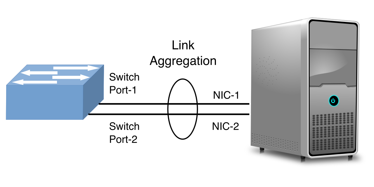
To ensure both sides of the connection agree on the bundle, protocols negotiate the link. The IEEE 802.3ad standard defines the Link Aggregation Control Protocol (LACP). The Link Aggregation Control Protocol allows switches to dynamically negotiate the creation of aggregated links, checking for configuration errors before actively sending data. If working in a strictly legacy Cisco environment, Port Aggregation Protocol (PAgP) is a proprietary link aggregation protocol that serves a similar function.
Crucial Implementation Rule: The physics of aggregation demand symmetry. All physical ports in a link aggregation group must share identical speed and duplex settings. You cannot bundle a 1Gbps link with a 10Gbps link.
Beneath all these protocols lies the fundamental unit of Ethernet traffic: the frame. The Maximum Transmission Unit (MTU) specifies the largest data payload that a network interface can transmit without fragmentation.
The default Ethernet Maximum Transmission Unit size is 1500 bytes. However, when we apply the VLAN technologies discussed earlier, the frame undergoes a slight physical change. Adding an 802.1Q VLAN tag increases the total maximum Ethernet frame size by four bytes. The payload remains 1500 bytes, but the overall frame on the wire stretches from 1518 bytes to 1522 bytes. Enterprise switches process this minor overhead natively.
Pushing the Limits with Jumbo Frames
In high-performance environments—like Storage Area Networks (SANs) transferring terabytes of database backups—chopping data into thousands of 1500-byte pieces generates massive CPU overhead. To solve this, engineers configure jumbo frames, which are Ethernet frames with a Maximum Transmission Unit larger than 1500 bytes. Jumbo frames typically support a Maximum Transmission Unit of up to 9000 bytes.

Jumbo frames act like massive freight trains: incredibly efficient, provided the tracks are built to handle them. All devices on a network segment must support jumbo frames to successfully transmit payloads larger than 1500 bytes.
If a 9000-byte frame arrives at an interface configured for a standard 1500-byte MTU, the switch behaves like a physical tunnel encountering a truck that is too tall: it destroys the payload. Consequently, mismatched Maximum Transmission Unit sizes between connected network switches cause dropped packets. This is a notorious troubleshooting trap for NOC analysts; the link will show "up," pings (which are tiny) will succeed, but large file transfers will mysteriously stall and fail.
By mastering how a switch handles logic (VLANs), pathways (STP/Trunks), and physics (MTU), you move beyond simply plugging devices into ports. You become the architect of an invisible, high-speed ecosystem.