Address Translation and Redundancy Protocols
Not sure you’re ready?
Take the ~3-minute readiness diagnostic and see where you stand.
Consider a massive corporate headquarters with ten thousand employees, yet the global postal service only grants the building a single public street address. When an employee mails a letter to the outside world, the corporate mailroom must intercept the envelope, erase the internal cubicle number, and stamp the building’s main address on the return line. When a reply arrives, the mailroom must reverse the process, examining its own records to route the letter back to the exact employee who initiated the correspondence.
Network engineering fundamentally relies on this exact principle. The internet does not know about the internal topology of an enterprise network, nor does it possess enough routing addresses to assign a unique identifier to every single laptop, smartphone, and server on the planet. Instead, network traffic is intelligently disguised, translated, and routed through edge devices that maintain the illusion of a seamless global network. Simultaneously, if that edge device—the corporate mailroom—were to catch fire, internal users would be entirely cut off from the outside world. To prevent this, engineers build invisible "phantom" routers that automatically assume routing duties the millisecond a primary device fails.
These twin concepts—address translation and first-hop redundancy—are the mechanisms that keep modern enterprise networks functional, scalable, and resilient.
The architecture of the internet was built upon IPv4, a 32-bit addressing scheme that yields approximately 4.3 billion unique IP addresses. By the 1990s, it became mathematically obvious that the proliferation of connected devices would rapidly exhaust this supply. Network Address Translation (NAT) was primarily developed to conserve the limited supply of public IPv4 addresses.
To achieve this conservation, Network Address Translation modifies IP address information in IPv4 packet headers while routing across a traffic device (typically a router or firewall). The router serves as the definitive boundary between a private, unroutable local area network and the public internet.
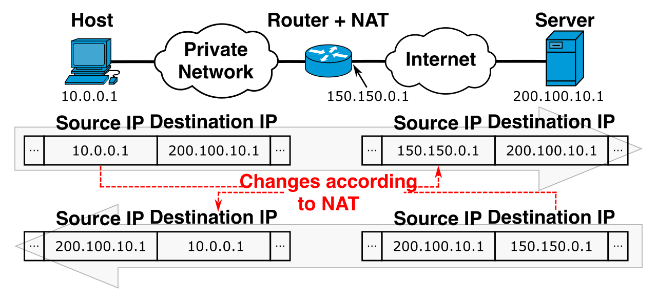
To understand NAT, you must understand how a router perceives IP addresses. The terminology is strictly defined by where the address lives and who is looking at it:
Inside Local Address: The actual private IP address assigned to a host on an internal network (e.g.,
192.168.1.50). The word "Local" means it is only valid locally.Inside Global Address: The public IP address representing one or more internal hosts to an outside network (e.g.,
203.0.113.5). The word "Global" means it is routable across the public internet.
When a packet traverses a NAT-enabled router, the router strips away the Inside Local source address and replaces it with an Inside Global address. It then records this translation in a NAT table so it knows exactly how to route the returning traffic.
The Three Methods of Source Translation
Administrators dictate exactly how private internal IP addresses are mapped to public addresses based on the needs of the network. There are three primary mechanisms for outbound traffic:
1. Static NAT
Static Network Address Translation maps a single private IP address to a single public IP address on a strict, one-to-one basis. If an internal web server must always appear to the internet as the exact same public IP, you configure Static NAT. However, because it requires dedicating one public IP for every private IP being translated, it does absolutely nothing to conserve IPv4 addresses.
2. Dynamic NAT
Dynamic Network Address Translation maps an internal private IP address to an available public IP address from a defined pool of addresses. If a company owns a block of 50 public IP addresses, the first 50 internal employees to access the internet will temporarily lease those public addresses. If employee 51 attempts to browse the web, their traffic is dropped until an address is freed up. It is more efficient than Static NAT, but still highly restrictive for large organizations.
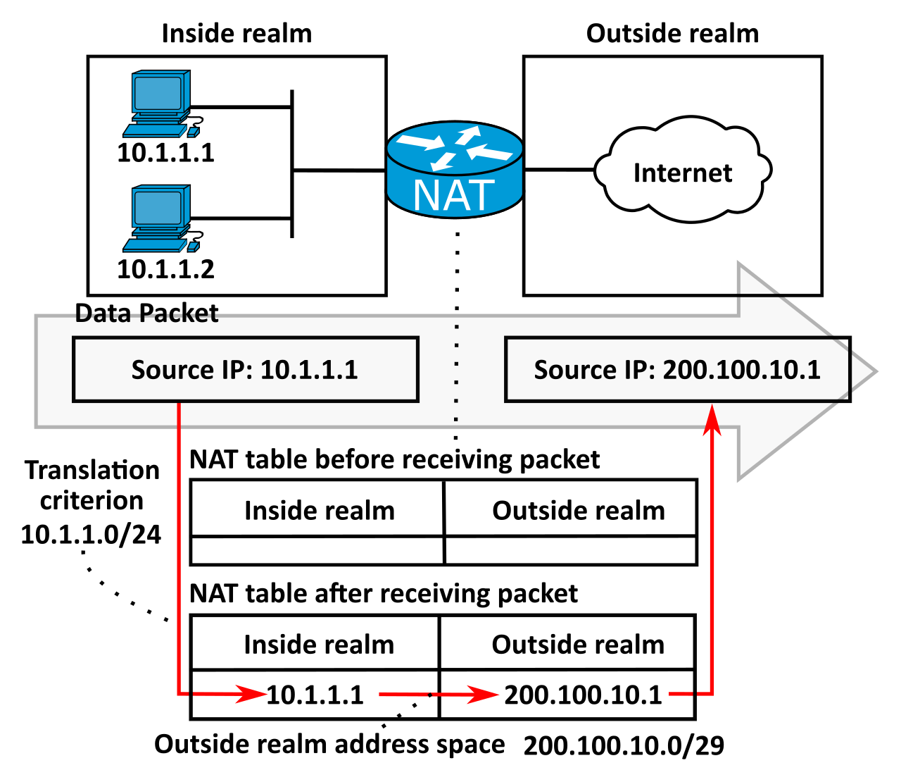
3. Port Address Translation (PAT)
If Dynamic NAT is a pool of guest passes, PAT is a master key. Port Address Translation maps multiple internal private IP addresses to a single public IP address using distinct source port numbers. Because of its sheer efficiency, Port Address Translation is frequently referred to as NAT Overload.
How does a router keep track of 5,000 internal laptops all sharing a single public IP address? Port Address Translation tracks individual internal host sessions by assigning a unique ephemeral port number to each outbound session.
- Laptop A sends a web request. The router translates the source to
203.0.113.5:50001. - Laptop B sends a web request. The router translates the source to
203.0.113.5:50002.
When the returning web traffic arrives at port 50002, the router checks its translation table, realizes this port was temporarily assigned to Laptop B, changes the destination IP back to Laptop B's Inside Local address, and forwards the packet. Because it must modify both the IP address and the TCP/UDP port, Port Address Translation operates at both the Network layer (Layer 3) and the Transport layer (Layer 4) of the Open Systems Interconnection (OSI) model.
Directing Traffic Inward: Destination NAT
Standard NAT alters the source address of traffic leaving the network. But what if an external user on the internet wants to access an internal resource, such as a company web server?
To accommodate this, engineers configure Destination Network Address Translation (DNAT). DNAT changes the destination IP address of inbound packets to route public traffic to a specific internal server. If a packet arrives at a router's public interface destined for port 443 (HTTPS), DNAT intercepts it and rewrites the destination IP to the internal, private IP of the web server. Because of this specific port-triggering behavior, Destination Network Address Translation is commonly known as port forwarding.
| Translation Type | Primary Purpose | Maps | Layer Operation |
|---|---|---|---|
| Static NAT | 1:1 consistent mapping for servers | 1 Private : 1 Public | Layer 3 |
| Dynamic NAT | Temporary internet access | 1 Private : 1 Public (from pool) | Layer 3 |
| PAT (NAT Overload) | Mass internet access | Many Private : 1 Public | Layers 3 & 4 |
| DNAT | Inbound access to internal resources | 1 Public : 1 Private | Layers 3 & 4 |
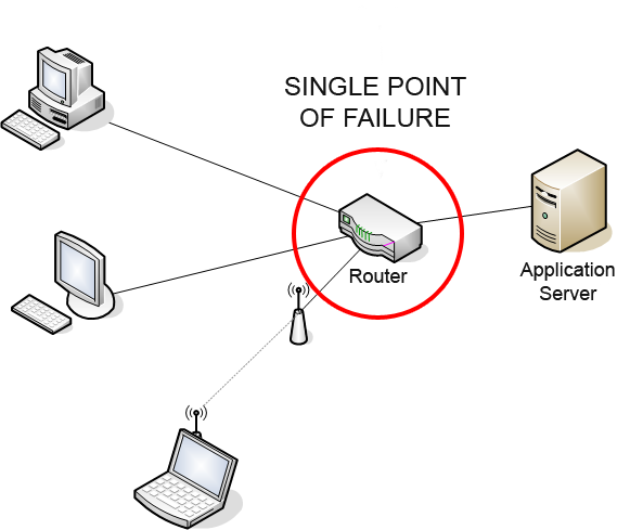
All of the routing and translation in the world is useless if the router itself suffers a catastrophic hardware failure. In a standard network design, every end host has a statically or dynamically assigned "Default Gateway"—the IP address of the router it uses to exit its local subnet. If that router loses power, the default gateway vanishes, and the entire subnet goes offline.
To eliminate this single point of failure, engineers utilize a First Hop Redundancy Protocol (FHRP). An FHRP provides transparent failover of a default gateway for end hosts on a local subnet. It achieves this by grouping multiple physical routers together to present the illusion of a single virtual router.
The Anatomy of the Illusion: Virtual IPs and MACs
You cannot configure host machines to use "Router A" as a gateway and expect them to magically know "Router B" exists when Router A catches fire. Instead, the network must handle the transition seamlessly.
This is accomplished using a Virtual IP (VIP) address, which is a logical IP address shared among multiple routers participating in a First Hop Redundancy Protocol group. Rather than pointing to a physical device, end hosts on a subnet must be configured to use the Virtual IP address of a redundancy group as their default gateway.
When a host wants to send traffic to the Virtual IP, it issues an Address Resolution Protocol (ARP) request to find the corresponding MAC address. First Hop Redundancy Protocols generate a virtual MAC address to respond to Address Resolution Protocol requests for the Virtual IP address.
The Failover Mechanism
Behind the curtain of this virtual IP and virtual MAC, the physical routers are constantly communicating with each other via "hello" packets. One router acts as the primary (or active) forwarder, physically processing the traffic sent to the virtual MAC.
Simultaneously, the other routers wait in the wings. A standby router automatically assumes traffic forwarding duties for the Virtual IP address if the primary router in a First Hop Redundancy Protocol group fails. Because the standby router instantly adopts the virtual MAC address, the end hosts are completely unaware that a physical failure ever occurred; their ARP tables do not need to update, and traffic continues flowing within milliseconds.
Standard FHRP Implementations
Depending on the network equipment vendor, an enterprise will implement one of three main redundancy protocols:
- Hot Standby Router Protocol (HSRP): A Cisco-proprietary First Hop Redundancy Protocol. It establishes an Active and a Standby router.
- Virtual Router Redundancy Protocol (VRRP): An open-standard First Hop Redundancy Protocol, allowing interoperability between different vendor hardware (e.g., a Juniper router and a Cisco router). It establishes a Master and Backup routers.
- Gateway Load Balancing Protocol (GLBP): A Cisco-proprietary First Hop Redundancy Protocol designed to provide both gateway redundancy and traffic load balancing. Unlike HSRP and VRRP, where the standby router sits completely idle, GLBP actively uses the bandwidth of all routers in the group by assigning multiple virtual MAC addresses to the same Virtual IP.
In modern enterprise environments, networks are logically segmented into Virtual Local Area Networks (VLANs). A switch isolates VLAN traffic at Layer 2; a device in the Sales VLAN cannot talk to a device in the Engineering VLAN without a router acting as an intermediary.
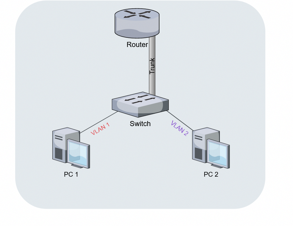
Historically, if a network had five VLANs, the switch required five separate physical cables connected to five separate physical ports on a router. This was an extraordinarily expensive and unscalable design. The solution was the router subinterface, a logical interface created by dividing a single physical router interface into multiple independent interfaces.
Network administrators configure router subinterfaces to enable inter-VLAN routing over a single physical link. Because a single cable extends from the switch to the router, resembling a stick with a piece of candy on top, inter-VLAN routing utilizing router subinterfaces is commonly referred to as a router-on-a-stick configuration.
Configuring the Router-on-a-Stick
To successfully implement router subinterfaces, several strict configuration requirements must be met at both the router and the connected switch:
- VLAN Tagging: Because the physical cable is carrying traffic from multiple VLANs simultaneously, the router must know how to distinguish the packets. Each router subinterface requires a specific 802.1Q VLAN tag to successfully process traffic for a specific Virtual Local Area Network. When a packet arrives, the router reads the 802.1Q tag, strips it, routes it to the correct destination subinterface, applies a new tag, and sends it back down the physical cable.
- Gateway Assignment: Just as a physical interface acts as a gateway for a subnet, each router subinterface acts as the default gateway for the client devices located within its assigned Virtual Local Area Network.
- IP Addressing: To route traffic, each router subinterface must be assigned an IP address belonging to the subnet of its corresponding Virtual Local Area Network. If VLAN 10 uses the
10.0.10.0/24subnet, SubinterfaceFastEthernet0/0.10might be assigned10.0.10.1. - Switch Trunking: The physical router is expecting tagged traffic. Therefore, a physical switch port connected to a router hosting subinterfaces must be configured as an 802.1Q trunk port. If the switch port is left in its default "access" mode, it will strip the VLAN tags before passing the traffic to the router, breaking the subinterface logic entirely.
By mastering how routers translate local addresses to the global stage, seamlessly mask hardware failures, and slice physical hardware into agile, logical interfaces, a network technician gains the foundational architecture skills required to maintain an enterprise network's lifeblood: continuous, highly available data transit.