Network Topologies and Architectures
Not sure you’re ready?
Take the ~3-minute readiness diagnostic and see where you stand.
If you lay out the streets of a metropolis without understanding where its inhabitants work, shop, and sleep, you guarantee gridlock. Computer networks demand the same architectural foresight. The copper and fiber optic cables pulling through a drop ceiling establish the physical layout, but the rules dictating how electrons and photons actually traverse those cables form an entirely different, logical map. Mastering network topologies and architectural models is not merely an exercise in memorizing diagrams; it is the study of how to move massive quantities of information with predictable latency, maximum resilience, and absolute control.
When you configure a switch port or trace an intermittent latency issue across a sprawling corporate campus, you are interacting directly with these blueprints. Let us examine the frameworks that keep modern infrastructure from collapsing under the weight of its own traffic.
To understand network design, we must first separate the hardware from the behavior.
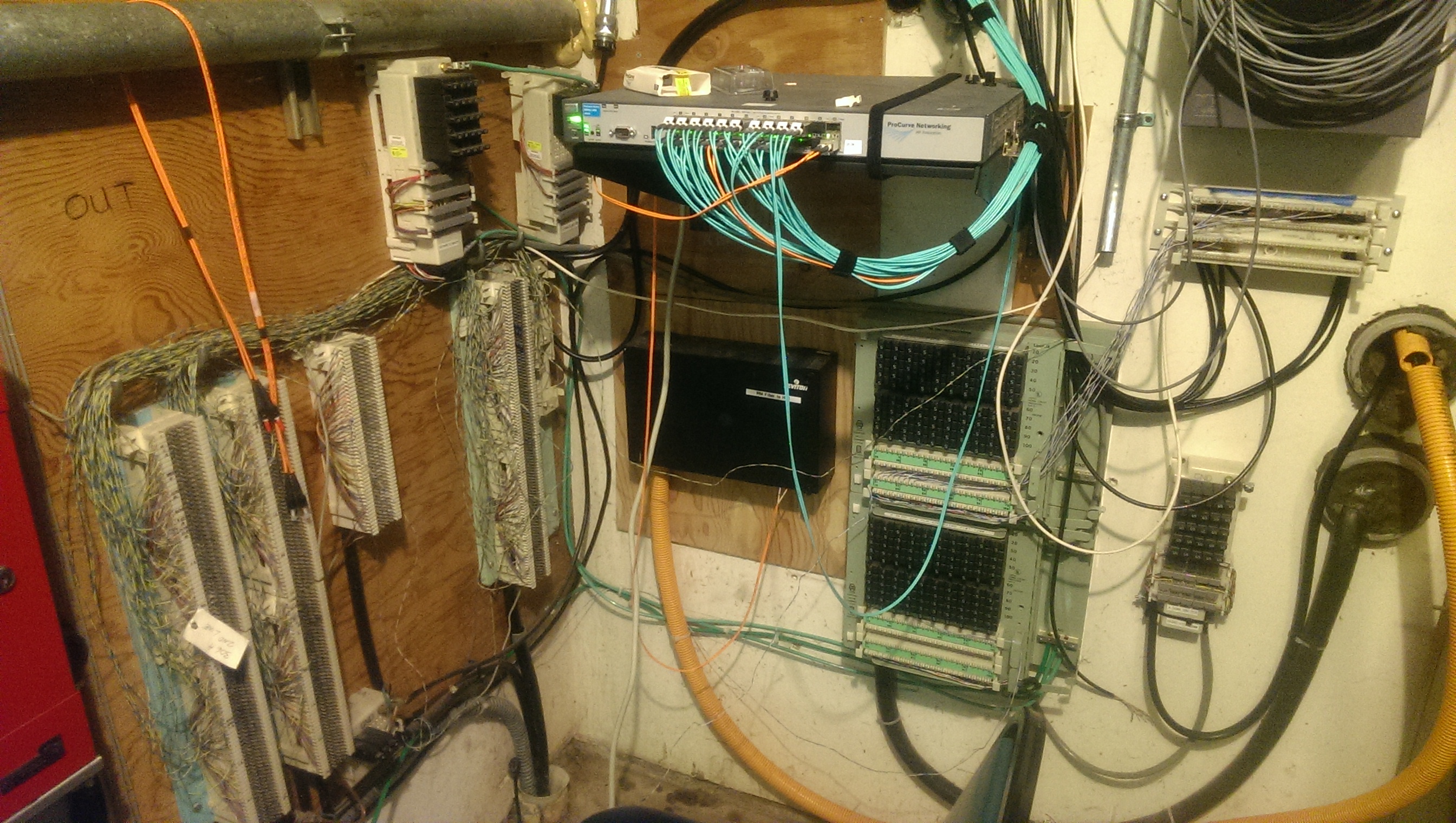
A physical topology describes the actual physical layout of network cables and hardware devices. If you were to walk through an office with a blueprint, tracing the blue Ethernet cables from the wall jacks to the patch panels in the telecom closet, you are mapping the physical topology.
Conversely, a logical topology describes how data flows through a network regardless of the underlying physical connections. For example, a network might be wired physically as a star, but logically pass data from node to node in a ring. As a network technician, you will frequently rely on the physical topology to know where to plug in a cable, but you will troubleshoot the logical topology to understand why a workstation cannot reach a server.
Every complex enterprise network is constructed from basic geometric building blocks. Understanding the strengths and fatal flaws of each is critical to diagnosing network behavior.
Point-to-Point Topology
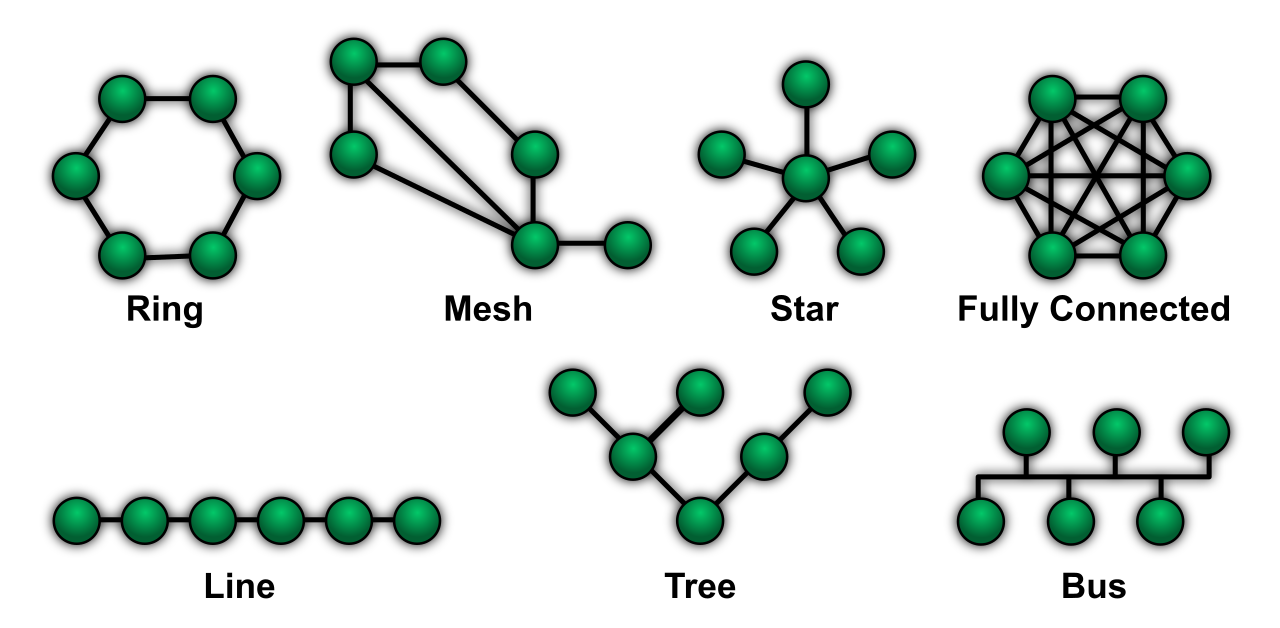
At its most fundamental level, networking is about connecting A to B. A point-to-point topology connects exactly two endpoints directly to each other. Because it uses a dedicated link without any intervening centralized distribution devices, it is highly efficient and secure. You will see this daily when linking a router to a modem, or when connecting two enterprise routers across a dedicated fiber optic leased line.
Star and Hub-and-Spoke Topologies
The vast majority of Local Area Networks (LANs) rely on a star topology, which connects all network endpoints to a single central connecting device, such as a switch. If you have ever plugged a laptop, a printer, and an IP phone into the same workgroup switch, you have built a star topology.
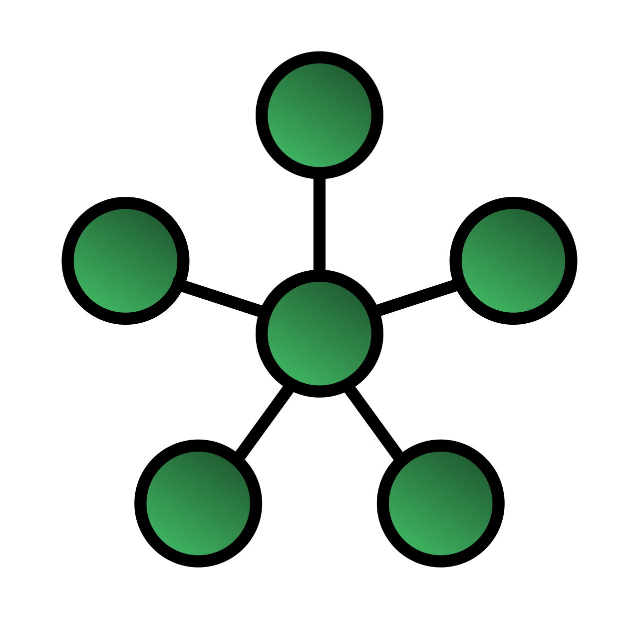
The advantage of a star is isolation: if one cable breaks, only that single device loses connectivity. However, this design inherently introduces a single point of failure at the central connecting switch or hub. If that central switch loses power, the entire network segment goes dark.
When we scale this concept across geographical distances, it becomes a hub-and-spoke topology. This model operates as the Wide Area Network (WAN) equivalent of a local area star topology. In a corporate environment, a hub-and-spoke topology routes all traffic from remote branch sites (the spokes) through a central headquarters site (the hub). If a branch office in Chicago needs to communicate with a branch office in Dallas, the data must first travel through the corporate headquarters in New York.
Mesh Topologies
When downtime is unacceptable—such as in banking or emergency services—architects turn to mesh topologies to eliminate single points of failure.
A full mesh topology connects every network node directly to every other node in the network. This provides maximum fault tolerance by ensuring multiple redundant paths exist between any two devices. If one link gets severed by a backhoe, routing protocols seamlessly redirect traffic over an alternate path.
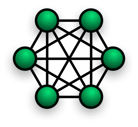
However, full mesh networks scale terribly. To understand why, look at the mathematics of network links:
The Mesh Connection Formula The formula to calculate the number of physical connections required in a full mesh network is n multiplied by n minus one, divided by two:
2n(n−1)
(Where n is the number of nodes).
If you have 5 routers, you need 10 connections. If you have 50 routers, you need 1,225 physical cables! To solve this scaling problem, engineers use a partial mesh topology. A partial mesh topology avoids the extreme physical complexity of a full mesh by not connecting every single node to every other node, while still providing multiple redundant connections between some critical nodes to improve resilience.
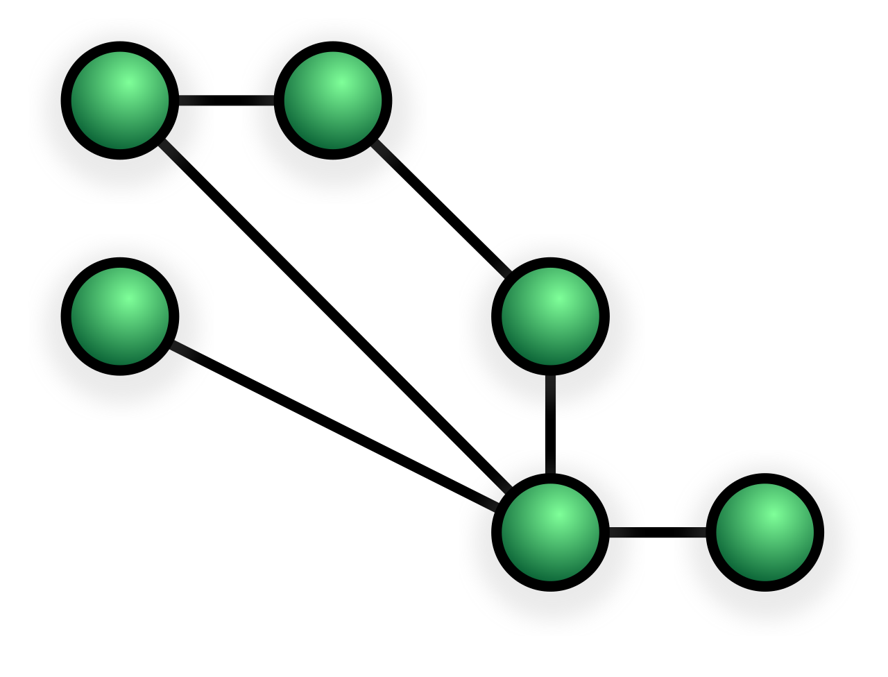
Hybrid Topologies
In reality, no modern enterprise relies on just one of these designs. A hybrid topology combines two or more different base physical or logical topologies into a single network structure. A university, for example, might use a partial mesh between its core campus buildings, but deploy star topologies inside each specific classroom.
Knowing the basic shapes of a network is not enough; we must organize them hierarchically so traffic can flow efficiently. For decades, the gold standard for campus and enterprise environments has been the three-tier hierarchical network design model.
The standard three-tier hierarchical network design model consists of the core layer, the distribution layer, and the access layer. Think of this like a national highway system: local streets (Access), regional highways with toll booths (Distribution), and massive interstate expressways (Core).
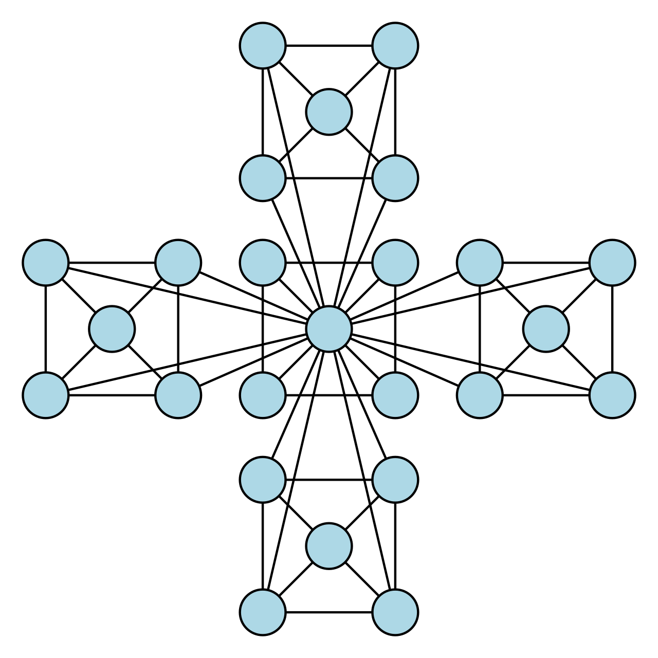
- The Access Layer: This is where the users live. The access layer in the three-tier model provides end-user devices with direct physical connection to the network. The switches you rack in an Intermediate Distribution Frame (IDF) closet that connect to desktop computers, printers, and wireless access points operate here.
- The Distribution Layer: The middleman. The distribution layer in the three-tier model aggregates traffic from multiple access layer switches. More importantly, this layer acts as the network's security and traffic cop. The distribution layer in the three-tier model enforces routing boundaries, access control lists (ACLs), and network policies. It decides whether traffic from the HR subnet is allowed to reach the Engineering subnet.
- The Core Layer: The backbone. Because the distribution layer handles all the heavy lifting of security policies and routing decisions, the core is optimized purely for speed. The core layer in the three-tier model functions as a high-speed backbone to switch traffic rapidly across the enterprise network.
| Tier | Primary Function | Real-World Hardware Example |
|---|---|---|
| Core | High-speed transport | Massive chassis switches routing fiber links between buildings |
| Distribution | Policy enforcement & Aggregation | Multilayer (Layer 3) switches handling inter-VLAN routing |
| Access | Endpoint connectivity | Gigabit PoE switches powering VoIP phones and PCs |
Before we explore how data centers are designed today, we have to look at how data is actually moving. We categorize network traffic directionally based on its origin and destination.
North-south network traffic describes data flowing from outside a data center to the inside of the data center, and conversely, describes data flowing from the inside of a data center to the outside network. External client requests connecting to data center servers typically generate north-south network traffic. When you stream a movie from a server to your smartphone over the internet, you are pulling traffic "south" out of that data center.
By contrast, east-west network traffic describes data flowing laterally between devices within a single data center or local network. Database queries from a web server to a backend database server within the same facility generate east-west network traffic.
For a long time, the internet was primarily north-south. A user requested a webpage, and the server delivered it. But the paradigm has shifted. The shift to modern distributed application architectures has caused data centers to experience predominantly east-west network traffic. Today, a single north-south request from a user's mobile app might trigger a cascade of hundreds of east-west microservice calls—checking inventory, authenticating tokens, logging analytics, and pulling database records—all before the server replies to the user.
The explosion of east-west traffic revealed a fatal flaw in the traditional three-tier model. If a server connected to an Access switch needed to talk to a server on a different Access switch, the data had to travel up to the Distribution layer, potentially up to the Core layer, back down to Distribution, and finally down to the target Access switch. This trombone-like routing caused unpredictable latency and severe bottlenecks.
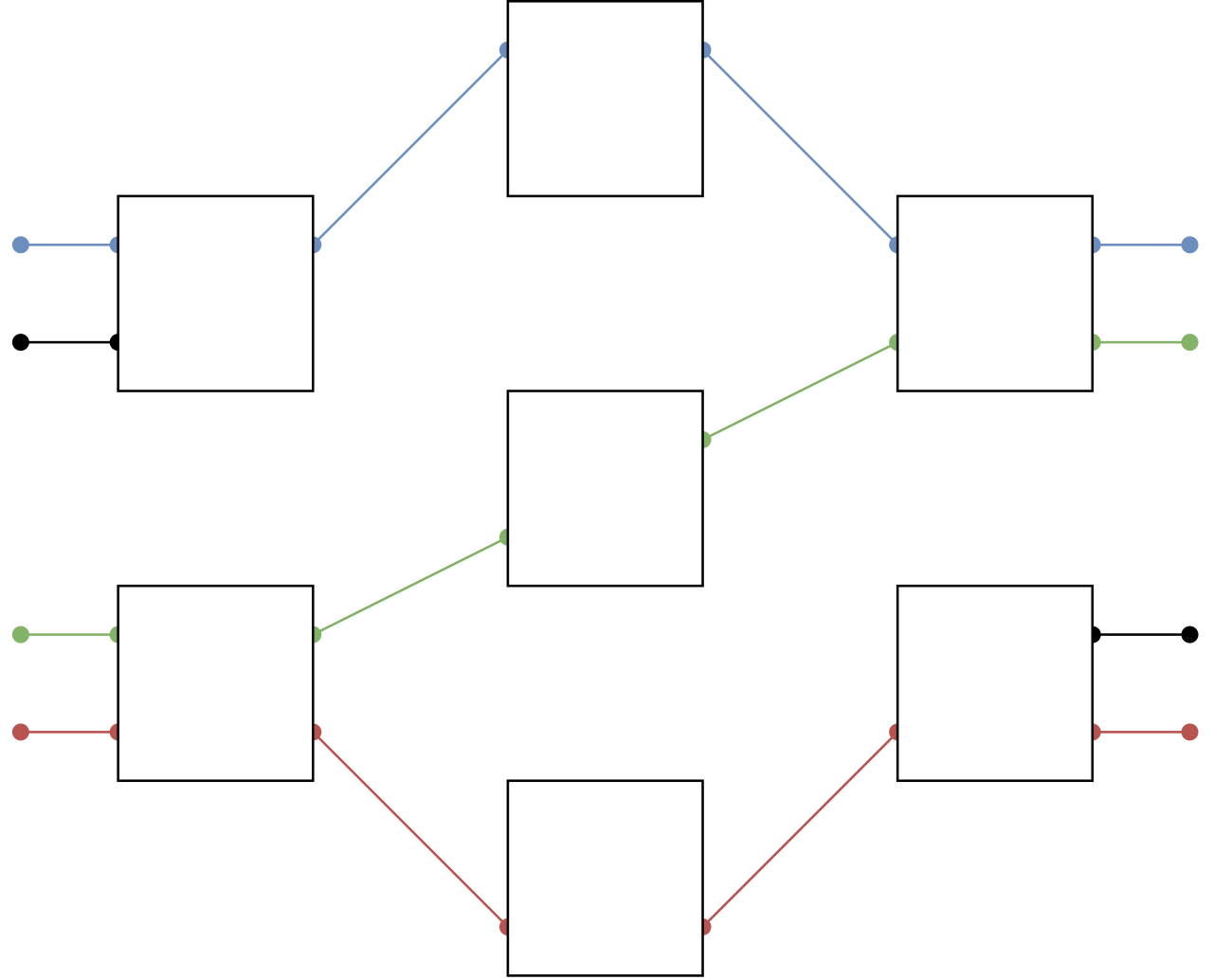
To fix this, the industry introduced a radically different framework. A spine-and-leaf architecture is a two-tier network design commonly deployed in modern data centers to optimize east-west traffic.
The rules of a spine-and-leaf design are mathematically rigid:
- Leaf switches in a spine-and-leaf architecture connect directly to endpoints such as servers and storage devices. (They function similarly to the old access layer).
- Every leaf switch in a spine-and-leaf architecture connects directly to every spine switch.
- Spine switches in a spine-and-leaf architecture only connect to leaf switches.
- Spine switches in a spine-and-leaf architecture never connect directly to end devices or servers.
Why This Matters for Performance
Because of this strict geometric arrangement, the spine-and-leaf architecture ensures that any endpoint is exactly the same number of network hops away from any other endpoint. Whether Server A is talking to Server B in the same rack, or Server Z across a massive warehouse facility, the traffic simply travels: Leaf → Spine → Leaf.
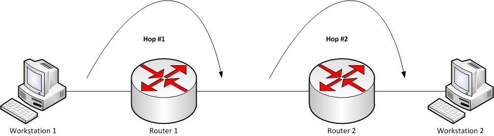
In the high-stakes world of modern infrastructure, unpredictability is the enemy. The consistent hop count in a spine-and-leaf architecture provides highly predictable latency for traffic flowing between servers. When configuring massive database clusters, virtualization environments, or AI training loads, this predictable, ultra-fast lateral movement is what keeps the entire operation running smoothly.
By understanding the physics of your topologies and the hierarchies of your architectures, you transition from someone who merely patches cables to an engineer who architects the flow of information itself.