Transceivers and Connector Types
Not sure you’re ready?
Take the ~3-minute readiness diagnostic and see where you stand.
At the foundational edge of every network, abstract data structures must be converted into physical reality. A packet traversing a global backbone is nothing but a mathematical concept until it is translated into a pulse of light or a burst of electrical voltage. As a network professional, your control over this physical layer dictates the reliability, speed, and integrity of the entire infrastructure. The transceivers that generate these signals, and the connectors that physically align them, are not mere accessories; they are the highly engineered optical and electrical bottlenecks through which all global communication flows.
To master networking, you must understand the physics of the connection. You will encounter environments where a millimeter of misalignment or an incorrect optical polish brings down a multi-million-dollar datacenter. This guide deconstructs the hardware responsible for transmitting our digital world.
Modern network switches and routers process data electrically, but transmitting data over long distances requires optics. It would be entirely impractical to hardwire a switch with permanent fiber-optic lasers—if a laser failed, or if you needed to upgrade your network speed, you would have to replace the entire switch.
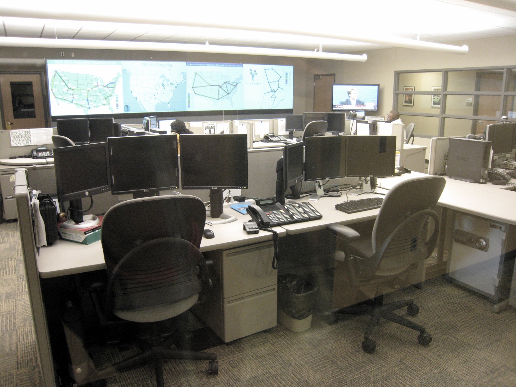
The industry solved this with modularity. We use transceivers—compact, interchangeable modules that plug directly into the equipment to handle the translation between electrical signals and whatever physical medium is leaving the rack. Crucially, these components are designed as hot-swappable transceivers, meaning they can be physically inserted or removed without powering down the host network device. This allows a NOC analyst to replace a failing optic on a live production switch without dropping a single packet on adjacent ports.
The SFP Family: 1 Gbps to 10 Gbps
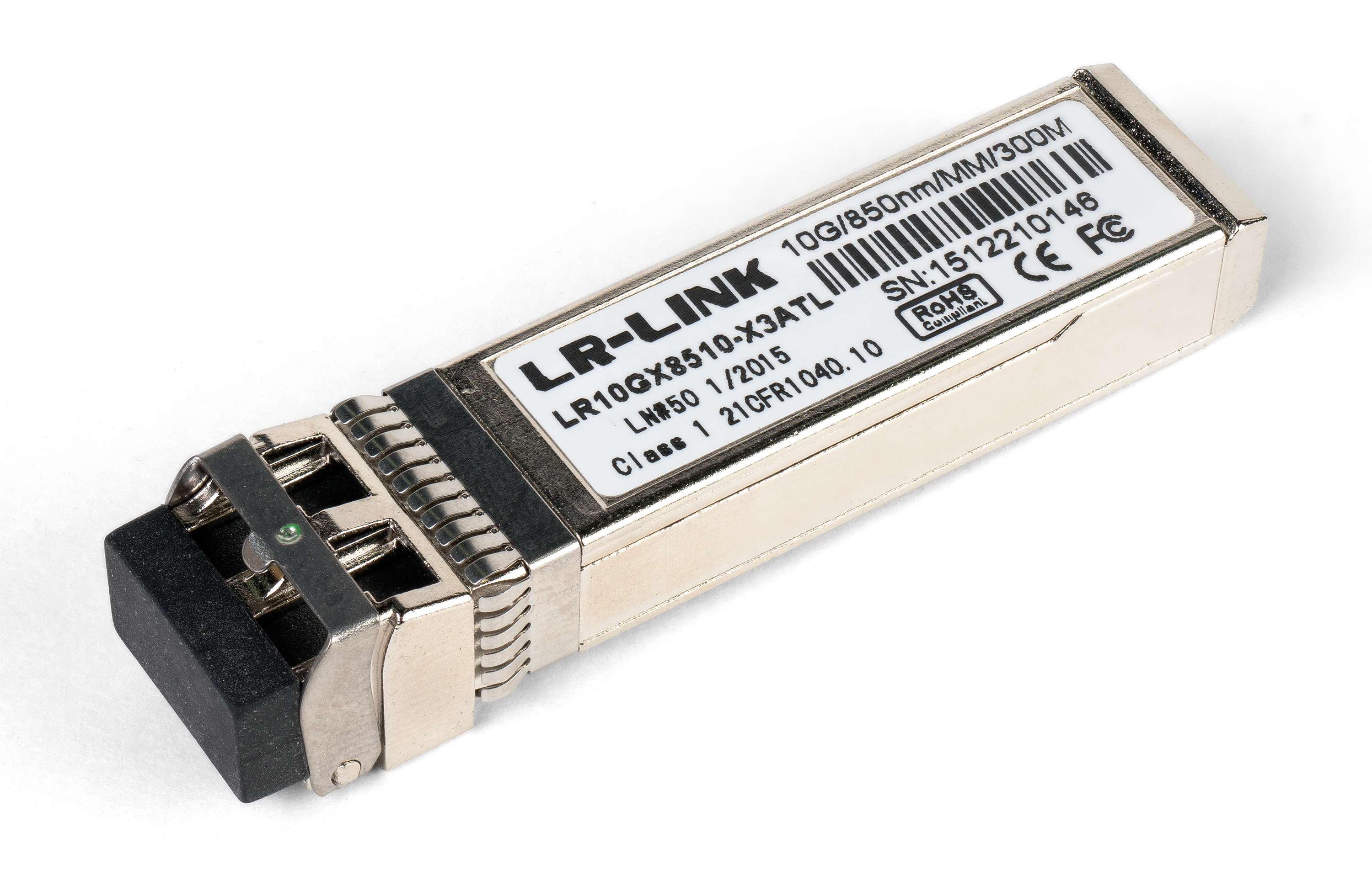
The most ubiquitous transceiver in modern networking is the Small Form-factor Pluggable (SFP).
- SFP: A standard SFP transceiver supports up to 1 Gbps data rates for Ethernet connections.
- SFP+: As network demands grew, the industry introduced the SFP+ transceiver, which supports data rates up to 10 Gbps.
A brilliant engineering decision was made here: an SFP+ transceiver shares the exact same physical dimensions as a standard SFP transceiver. This means switch manufacturers can design a single port chassis that accepts either module. Beyond standard Ethernet traffic, both SFP and SFP+ transceivers are commonly used for high-speed Fibre Channel storage area networks (SANs), providing the ultra-low latency required by enterprise storage arrays.
The QSFP Family: Multiplying Bandwidth
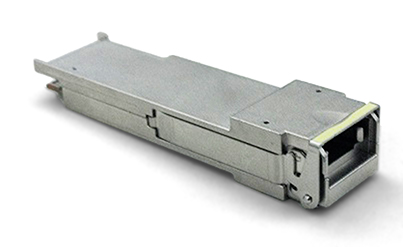
When 10 Gbps is no longer sufficient, we do not simply spin a laser faster; we parallelize the transmission. This is the operating principle behind the Quad Small Form-factor Pluggable (QSFP) transceiver.
The word "Quad" is literal. A QSFP transceiver contains four individual transmit and receive channels.
- A standard QSFP transceiver typically supports 4 Gbps total bandwidth by combining four individual 1 Gbps channels.
- By upgrading the internal channels, a QSFP+ transceiver typically supports 40 Gbps total bandwidth by combining four individual 10 Gbps channels.
Why this matters to you: When you look at a QSFP+ port, you are not looking at one massive 40 Gbps pipe; you are looking at four parallel 10 Gbps lanes operating in unison. Many network administrators use "breakout cables" to split a single 40 Gbps QSFP+ port on a core switch into four separate 10 Gbps SFP+ connections for downstream servers.
Bidirectional (BiDi) Transceivers
Standard fiber optic communication requires two strands of glass: one to transmit (Tx) and one to receive (Rx). But what if you are leasing underground fiber from an ISP, and a second strand doubles your monthly cost?
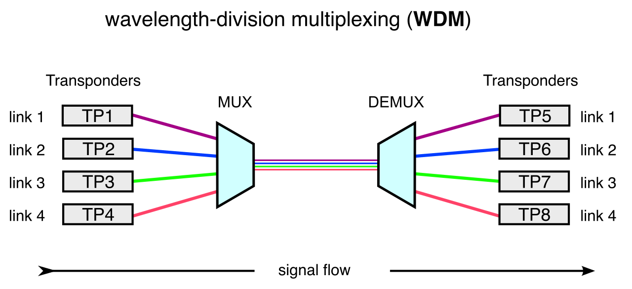
You rely on physics. Bidirectional (BiDi) transceivers allow full-duplex communication over a single fiber optic strand. How do they achieve this without the signals colliding and causing interference? They employ Wavelength Division Multiplexing (WDM). A BiDi transceiver uses WDM to transmit and receive signals simultaneously on different light wavelengths (different "colors" of light). For example, the transceiver on one end might transmit using a 1310nm wavelength and receive on a 1490nm wavelength, while the transceiver on the exact opposite end is tuned to do the reverse.
Once the transceiver fires a laser, the light must be coupled seamlessly into a glass core that is often smaller than a human hair (9 microns for single-mode fiber). The connector at the end of the fiber-optic patch cable is responsible for this microscopic alignment. The glass is held rigidly inside a ceramic or plastic cylinder called a ferrule.
Legacy and Current Duplex Connectors
As fiber optic technology has evolved, connectors have shrunk to allow higher port density on network equipment.
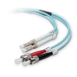
- ST Connector: The Straight Tip (ST) fiber connector uses a bayonet-style twist-and-lock coupling mechanism. To lock it, you push it in and twist the outer ring, much like putting a cap on a medicine bottle. Because of this twisting motion, ST connectors require significant finger space, making them unsuitable for dense, modern network switches.
- SC Connector: The Subscriber Connector (SC) fiber connector uses a push-pull insertion mechanism with a square plastic body. It snaps in and pulls out cleanly. An SC fiber connector has a 2.5mm ferrule. While popular in enterprise networks for decades, the 2.5mm size proved too bulky for massive datacenter expansion.
- LC Connector: The Lucent Connector (LC) was engineered for high density. An LC fiber connector uses a latching mechanism structurally similar to a copper RJ-45 connector. You push it until it clicks, and press a small plastic tab to release it. Because an LC fiber connector has a 1.25mm ferrule—exactly half the size of the SC—you can fit twice as many LC connections in the same physical rack space.
High-Density and Multi-Fiber Connectors
When datacenters shifted to 40 Gbps and 100 Gbps backbones, managing hundreds of individual LC cables became an organizational nightmare. The solution was to combine multiple fiber strands into single, unified connectors.
- MT-RJ: The Mechanical Transfer Registered Jack (MT-RJ) is a duplex fiber optic connector with a footprint similar to an RJ-45 connector. Instead of two separate ceramic ferrules, it houses two fiber strands inside a single polymer ferrule.
- MPO: For extreme density, the industry uses the Multi-Fiber Push-On (MPO) connector. An MPO connector terminates multiple optical fibers inside a single rectangular ferrule. MPO connectors typically terminate 12 or 24 individual optical fibers in one plug. Because QSFP+ transceivers require four transmit and four receive lanes (8 fibers total), MPO connectors are frequently used for high-bandwidth 40 Gbps and 100 Gbps network backbone connections.
| Connector | Mechanism | Ferrule / Characteristic | Common Use Case |
|---|---|---|---|
| ST | Twist-and-lock (Bayonet) | 2.5mm | Legacy installations, industrial environments |
| SC | Push-pull (Square body) | 2.5mm | Older enterprise runs, telecom demarcations |
| LC | Latching (like RJ-45) | 1.25mm | Standard for modern SFP/SFP+ transceivers |
| MPO | Push-pull | Rectangular (12-24 fibers) | 40G/100G QSFP backbones |
When two fiber connectors meet, the glass cores touch. If the cut is imperfect, a tiny air gap causes some of the laser light to reflect backward. Light reflecting back into the transceiver's laser source causes "Return Loss," which destabilizes the signal and degrades network performance.
To manage this, the end-faces of the fiber cores are precisely polished at the factory.
Ultra Physical Contact (UPC) Ultra Physical Contact (UPC) connectors feature a flat-polished fiber end face. While "flat" to the naked eye, it actually has a microscopic dome shape to ensure the cores touch first. However, if light does reflect off a UPC face, it bounces straight backward, directly down the core toward the source. To help you quickly identify them in a datacenter, UPC fiber connectors are standardly color-coded blue.
Angled Physical Contact (APC) In environments where signal reflection is entirely unacceptable (such as long-haul single-mode links, or analog video over fiber), we use APC. Angled Physical Contact (APC) connectors feature a fiber end face polished at an 8-degree angle.
The Physics of APC: The 8-degree angle in an APC connector prevents reflected light signals from traveling back down the fiber optic core. Instead of bouncing straight back, the physical angle forces any reflected light to bounce off into the outer cladding of the fiber, where it harmlessly dissipates.
Because plugging an angled APC connector into a flat UPC port would crush the delicate glass tips, visual identification is critical: APC fiber connectors are standardly color-coded green.
Optical networking dominates the backbone, but copper cables—transmitting data via electrical voltage—remain the undisputed kings of the network edge, connecting desktops, access points, and endpoints.
Twisted-Pair Connectors
Twisted pair cabling relies on the concept of modular "Registered Jack" (RJ) connectors.
- RJ-11: The granddaddy of telecom. An RJ-11 copper connector has six positions and typically houses two or four metal contacts (often referred to as 6P2C or 6P4C). Because of its limited pinout, RJ-11 connectors are predominantly used to terminate analog telephone lines and older dial-up modem links.
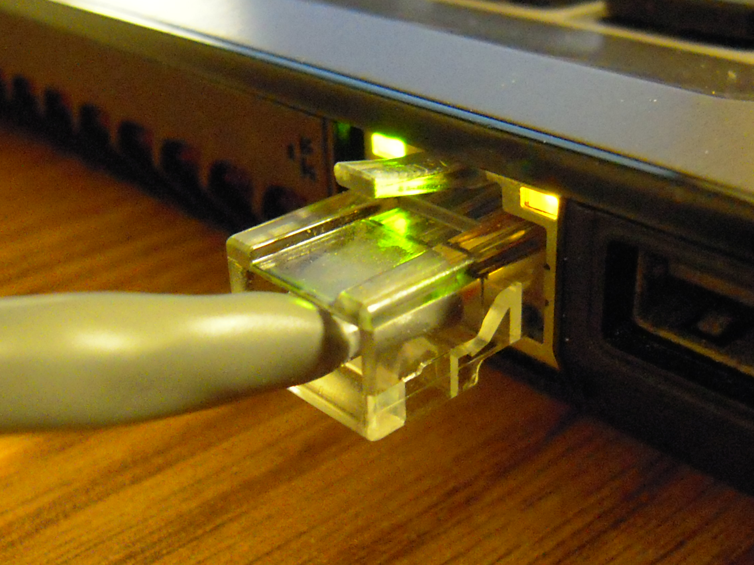
- RJ-45: The bedrock of local area networking. An RJ-45 copper connector has eight positions and eight metal contacts (8P8C). Every time you plug a standard Ethernet cable into a computer, you are using this connector. RJ-45 connectors are the standard physical interface for twisted-pair Ethernet networks, carrying everything from standard 10 Mbps traffic up to multi-gigabit PoE (Power over Ethernet) connections.
Coaxial / RF Connectors
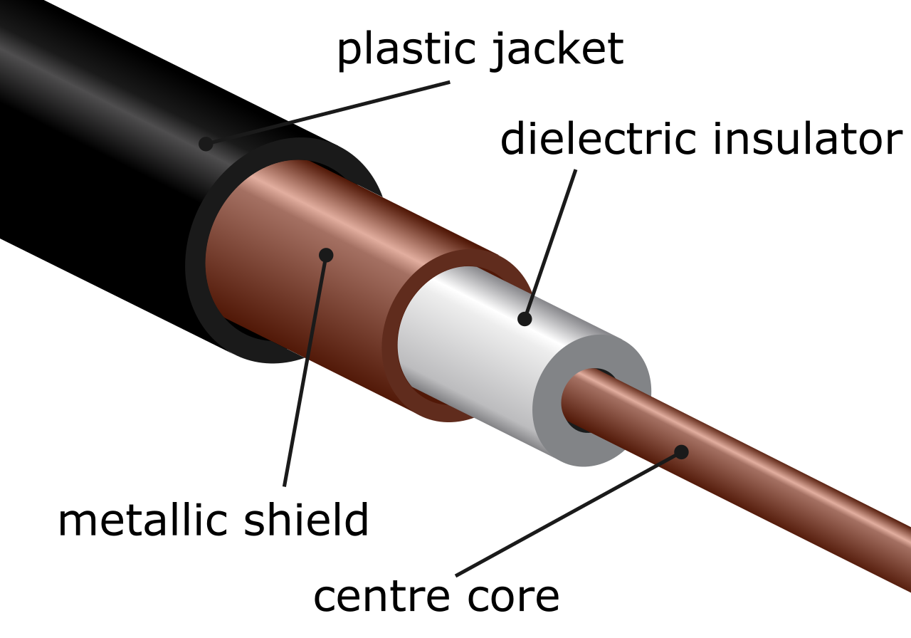
Coaxial cables operate differently than twisted pairs; they consist of a single central copper conductor surrounded by heavy shielding. They are designed to carry Radio Frequency (RF) signals over long distances with minimal electromagnetic interference.
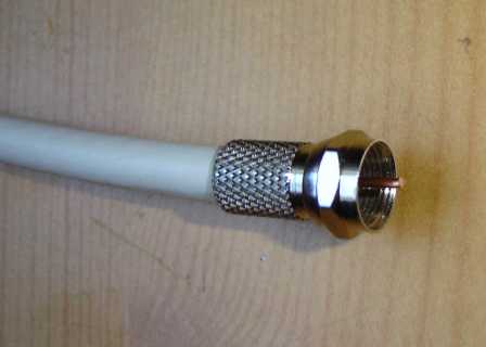
- F-Type: If you have ever set up a home internet connection, you know this one. An F-type connector uses a threaded screw-on mechanism to secure a coaxial cable to a network device. Because the threaded mechanism provides an incredibly tight, weather-resistant physical bond, F-type connectors are widely used for cable television networks and DOCSIS broadband cable modem connections.
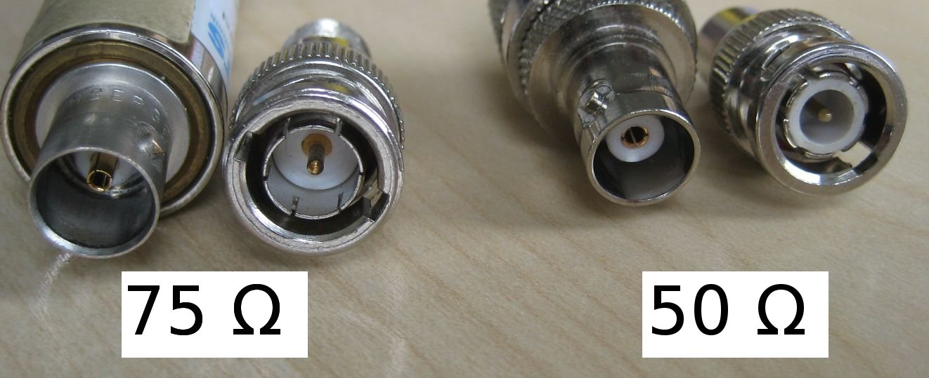
- BNC: The Bayonet Neill-Concelman (BNC) connector uses a twist-and-lock mechanism to secure a coaxial cable. Notice the mechanical similarity to the fiber-optic ST connector mentioned earlier: you push it on and twist a quarter-turn to lock it securely onto the port's locking pins. Historically, BNC connectors are commonly used for analog video applications and legacy 10Base2 Ethernet networks. While you will rarely build a new 10Base2 network today, you will still encounter BNC heavily in physical security environments connecting CCTV cameras to DVRs.
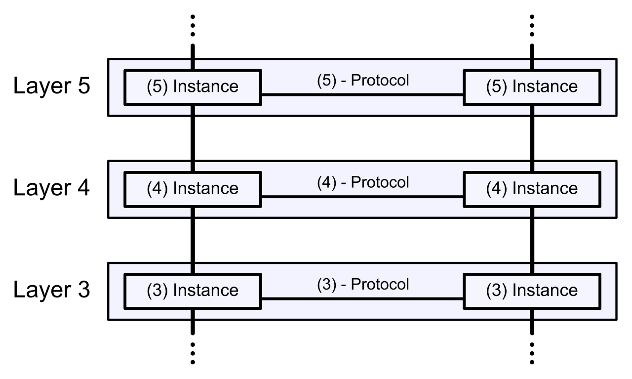
As a system administrator or NOC analyst, your troubleshooting workflow almost always begins at Layer 1 of the OSI model. If the physical layer fails, the upper layers collapse. By understanding exactly how a QSFP+ module aggregates 40 Gbps of traffic, why an LC connector saves rack space, why you must never plug a green APC cable into a blue UPC port, and exactly which copper interface connects a DOCSIS modem versus a switch, you transform from someone who just "plugs things in" to a professional who engineers the infrastructure.