Wireless and Wired Transmission Media
Not sure you’re ready?
Take the ~3-minute readiness diagnostic and see where you stand.
At the foundational layer of any network infrastructure, every database query, video call, and encrypted payload must ultimately be reduced to a physical phenomenon. To move data from one point to another, we encode it into an electrical voltage, a pulse of light, or an electromagnetic radio wave. As a network professional, your ability to design, build, and troubleshoot systems depends entirely on understanding the physical properties, constraints, and operational realities of these transmission media. When a server goes offline, or a hospital wing loses connectivity, the root cause is frequently not a complex routing loop, but a physical limitation of the medium itself—a cable run exceeding its maximum distance, an electromagnetic frequency saturated with interference, or an incorrect cable jacket degrading the environment.
We will evaluate the standard transmission media you will handle daily, breaking them down by their physical properties, their performance thresholds, and the strict safety codes governing their deployment.
Wireless networking frees devices from the physical tether of copper cables, but it binds them to the strict physics of the electromagnetic spectrum. Local Area Network (LAN) wireless standards are defined by the IEEE 802.11 working group. Over the decades, these standards have evolved to manipulate radio frequencies with increasing efficiency.
Frequency and Bandwidth Evolution
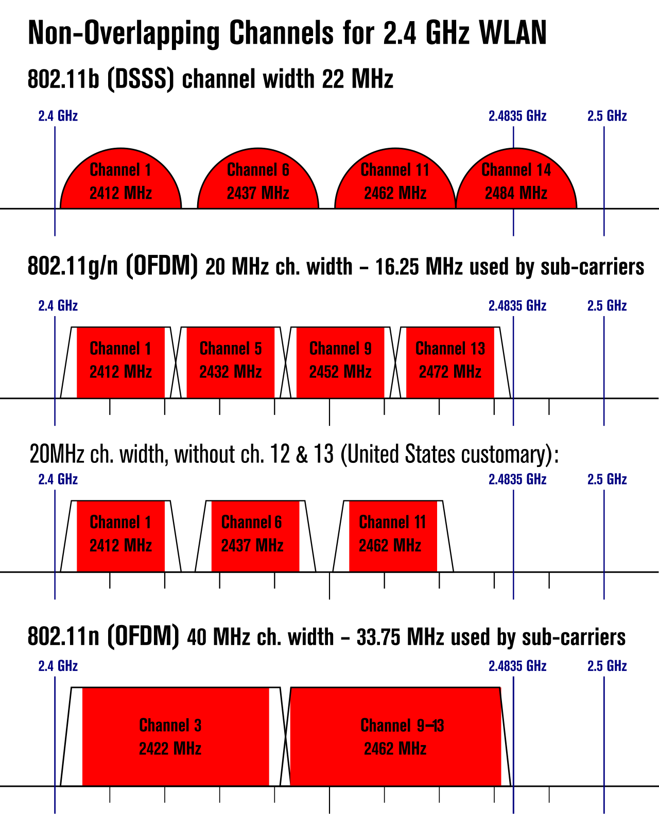
The earliest prevalent standards established the foundation. The IEEE 802.11a wireless standard operates exclusively in the 5 GHz frequency band and supports a maximum theoretical bandwidth of 54 Mbps. Because 5 GHz waves are relatively short, they struggle to penetrate dense walls. Conversely, the IEEE 802.11b wireless standard operates exclusively in the 2.4 GHz frequency band, which offers better physical penetration but is crowded with interference from microwaves and Bluetooth devices. 802.11b supports a maximum theoretical bandwidth of 11 Mbps.
Engineers subsequently improved the 2.4 GHz space with the IEEE 802.11g wireless standard. Operating within that same 2.4 GHz frequency band, it supports a maximum theoretical bandwidth of 54 Mbps and was designed to be backwards compatible with the older 802.11b standard, allowing seamless upgrades for existing hardware.
Modern Wi-Fi Generations
As bandwidth demands skyrocketed, the Wi-Fi Alliance recognized that "802.11" nomenclature was confusing for consumers and introduced generational naming.
| IEEE Standard | Wi-Fi Name | Frequencies | Max Theoretical Bandwidth | Key Technological Innovation |
|---|---|---|---|---|
| 802.11n | Wi-Fi 4 | 2.4 GHz & 5 GHz | 600 Mbps | MIMO (Multiple Input Multiple Output) antenna technology. |
| 802.11ac | Wi-Fi 5 | 5 GHz exclusively | Gigabit+ | MU-MIMO (Multi-User MIMO) for simultaneous downstream transmissions. |
| 802.11ax | Wi-Fi 6 | 2.4 GHz & 5 GHz | Multi-Gigabit | OFDMA (Orthogonal Frequency-Division Multiple Access). |
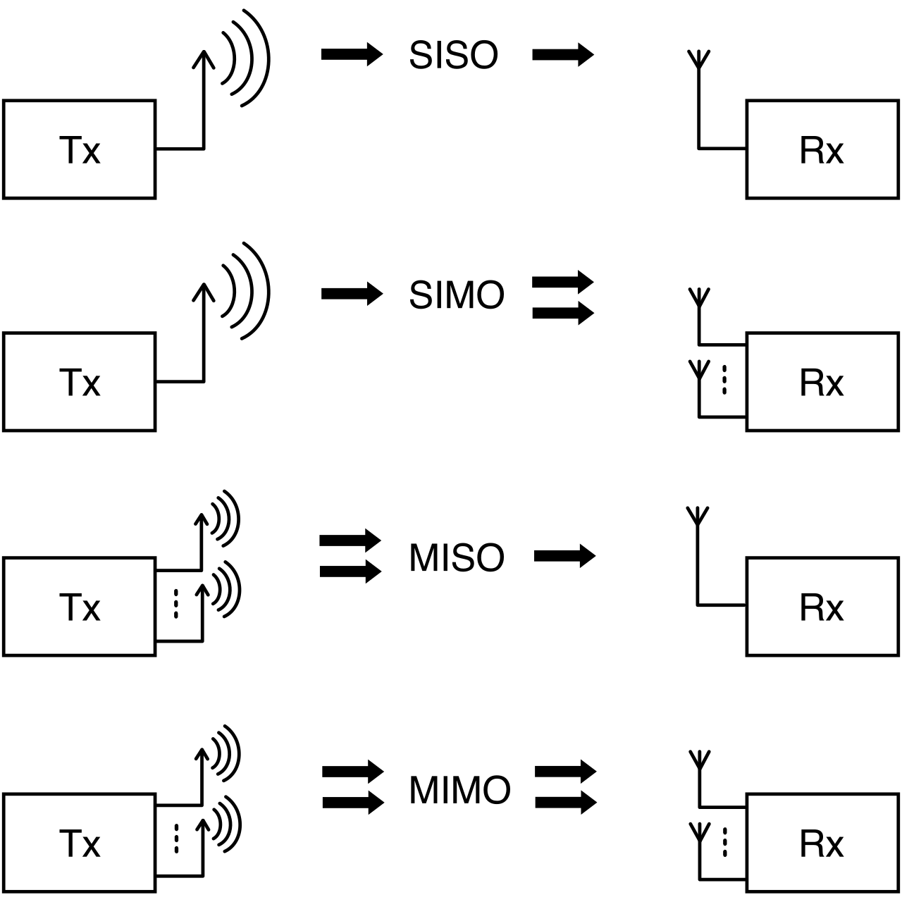
Why it matters: Understanding the innovations is crucial for deployment. 802.11n introduced Multiple Input Multiple Output (MIMO) antenna technology, allowing access points to use multiple antennas to send and receive separate data streams simultaneously—multiplying capacity like adding lanes to a highway. Later, 802.11ac introduced Multi-User MIMO (MU-MIMO) technology for simultaneous downstream transmissions, meaning a router could talk to your laptop and your smartphone at the exact same millisecond.
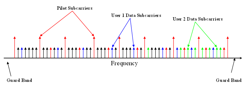
The most recent shift is 802.11ax, formally designated as Wi-Fi 6. It operates in both the 2.4 GHz and 5 GHz frequency bands. To handle dense environments like auditoriums or crowded offices, Wi-Fi 6 utilizes Orthogonal Frequency-Division Multiple Access (OFDMA). OFDMA in Wi-Fi 6 allows a single transmission to carry data for multiple devices by dividing channels into smaller subcarriers. Imagine a delivery truck that can carry packages for dozens of houses on a single street trip, rather than making a separate trip for each package. Furthermore, to escape the congestion of legacy bands, the Wi-Fi 6E specification was introduced as an extension of the 802.11ax standard that utilizes the 6 GHz frequency band.
When terrestrial cables or local Wi-Fi cannot reach a device, we rely on wide-area wireless networks.
Cellular Networks
Cellular networks operate via vast webs of cellular towers. Cellular 4G Long Term Evolution (LTE) networks theoretically support download speeds up to 1 Gbps. However, modern infrastructure is transitioning rapidly to 5G.
Cellular 5G networks theoretically support download speeds up to 20 Gbps and utilize low-band, mid-band, and millimeter-wave (mmWave) frequency spectrums. The physics of these bands dictate their use cases:
- Millimeter-wave 5G provides the highest cellular bandwidths over very short physical distances. Because the waves are so small, they are easily blocked by trees, rain, or glass.
- Low-band 5G provides the greatest physical coverage area while offering the lowest cellular bandwidths. Its large waves easily travel miles and bend around physical obstacles.
Satellite Internet
For remote facilities, maritime operations, or extreme rural locations, satellite is often the only option. However, satellite internet connections experience significantly higher latency compared to terrestrial wired or cellular networks due to the physical distance the signal must travel. Even at the speed of light, traveling to space and back takes noticeable time.
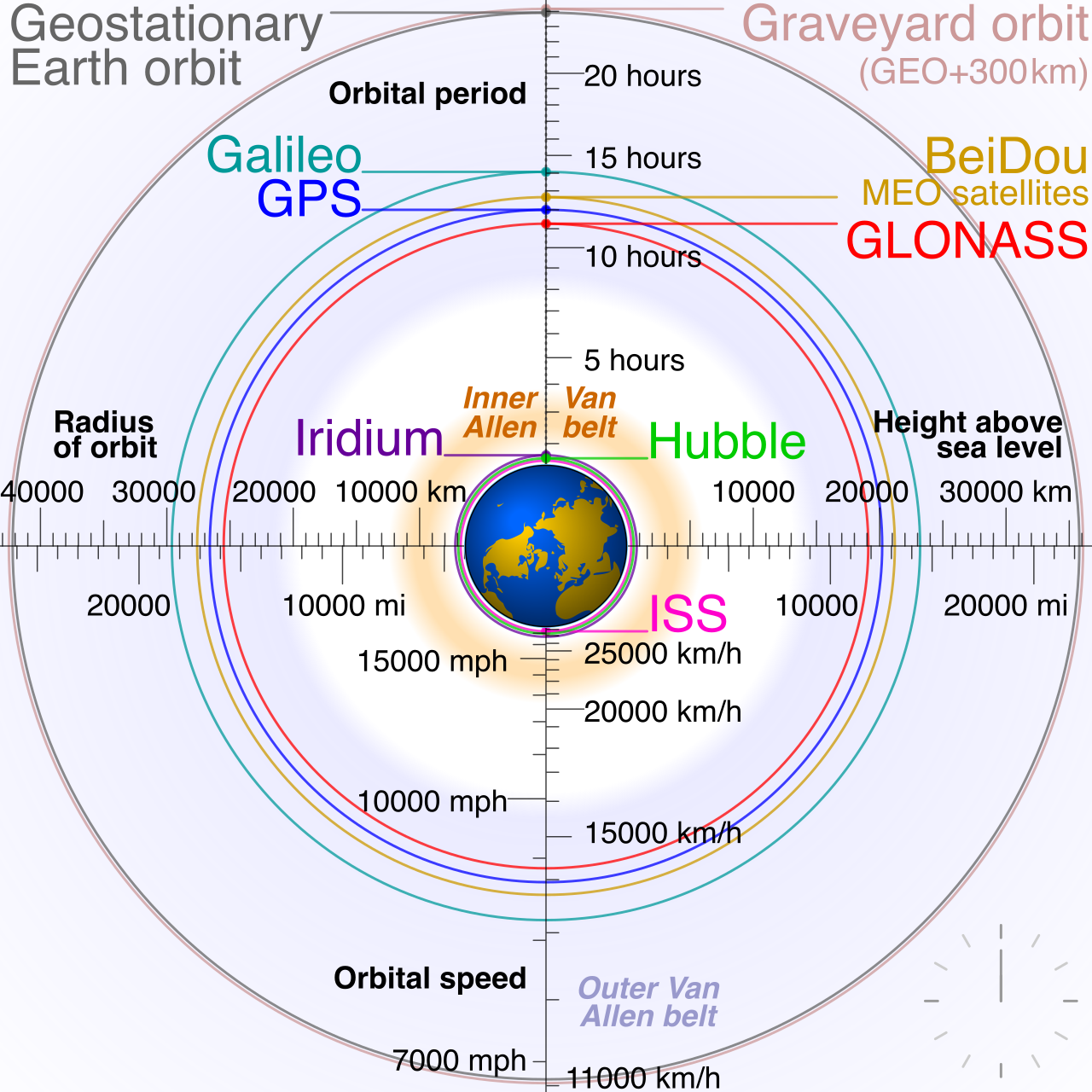
- Geostationary Earth Orbit (GEO) satellites orbit at approximately 35,786 kilometers above the Earth's equator. They remain fixed over a single spot on Earth, but the extreme distance yields massive latency.
- Low Earth Orbit (LEO) satellite internet constellations orbit closer to the Earth than GEO satellites. Consequently, LEO satellite systems provide much lower communication latency than GEO satellite systems.
Regardless of the orbit, RF signals traversing the atmosphere have a critical weakness: Satellite internet signals are susceptible to attenuation caused by atmospheric conditions like rain, snow, and heavy cloud cover. As an IT generalist, you must account for localized "weather fades" when managing satellite failover links.
Within the enterprise, the vast majority of endpoint devices are connected via copper cabling. The IEEE 802.3 standard family defines Ethernet wired networking technologies.
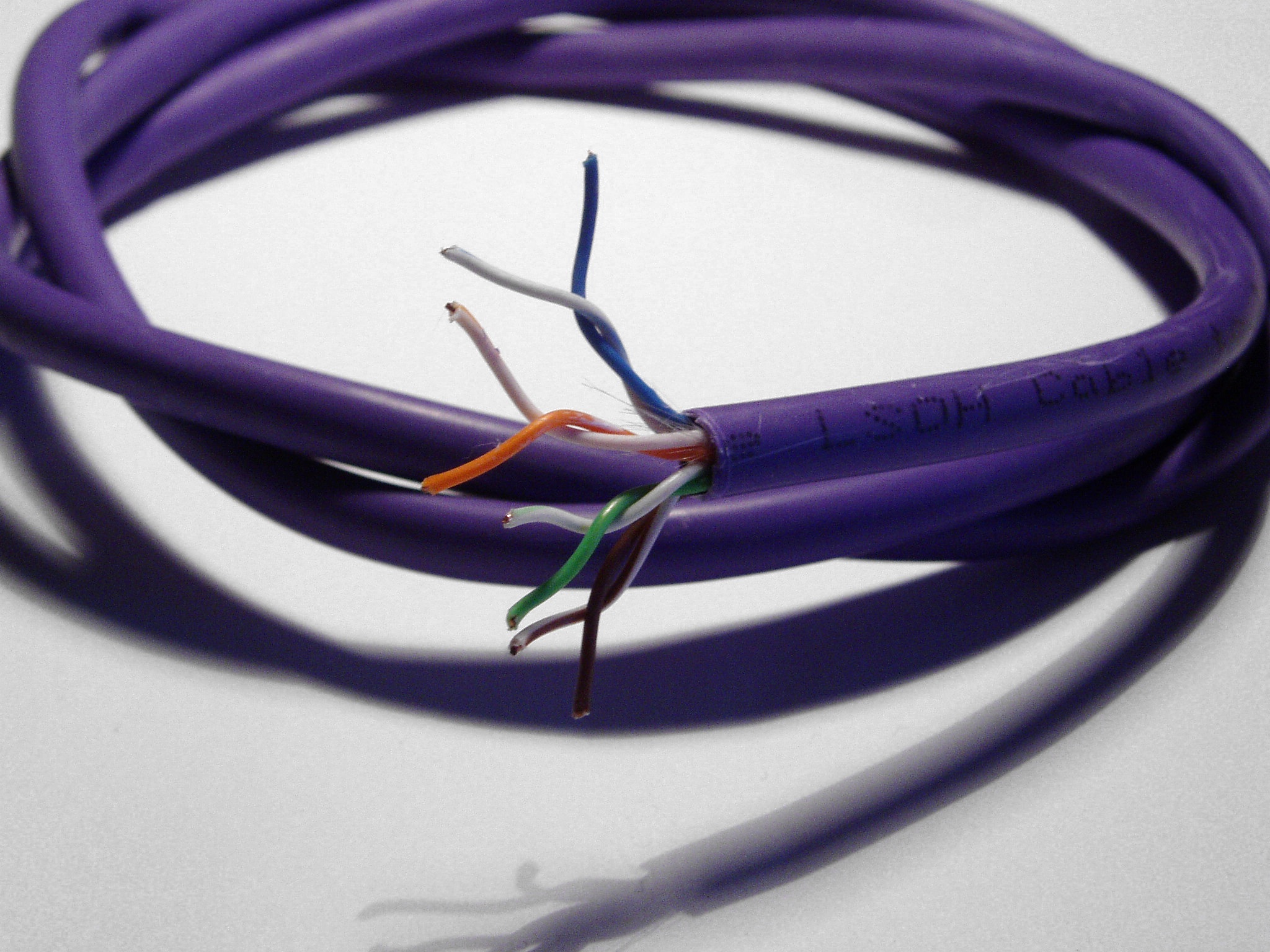
Copper cables utilize varying twisting techniques to cancel out Electromagnetic Interference (EMI). However, electrical resistance within the copper eventually degrades the signal. Therefore, twisted-pair copper Ethernet cables have a maximum standard run length of 100 meters.
Ethernet BASE-T Standards
| Standard | Max Speed | Medium | Max Distance |
|---|---|---|---|
| 10BASE-T | 10 Mbps | Twisted-pair copper | 100 meters |
| 100BASE-TX | 100 Mbps | Twisted-pair copper | 100 meters |
| 1000BASE-T | 1 Gbps | Twisted-pair copper | 100 meters |
| 10GBASE-T | 10 Gbps | Twisted-pair copper | Varies by cable category |
To meet these speeds, cables are manufactured to different Category ratings with tighter twists and better shielding:
- Category 5e (Cat5e) twisted-pair cable supports 1 Gbps networking up to 100 meters.
- Category 6 (Cat6) twisted-pair cable supports 10 Gbps networking up to a maximum distance of 55 meters. (If you push 10 Gbps beyond 55 meters on Cat6, physics dictates you will experience dropped packets and port errors).
- Category 6a (Cat6a) twisted-pair cable supports 10 Gbps networking up to a maximum distance of 100 meters.
Specialized Copper: Twinaxial and Coaxial
Not all copper is twisted pair. Sometimes the application requires a different physical construction.
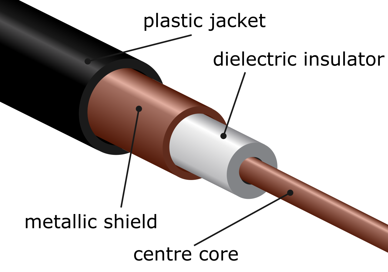
Coaxial Cables You have likely seen these in residential setups. Coaxial cables contain a single inner copper conductor surrounded by a tubular insulating layer and a metallic shield. This thick shielding makes them highly resistant to interference.
- RG-6 coaxial cables are heavily utilized by telecommunications providers for cable television and broadband internet connections.
- RG-59 coaxial cables are commonly used for short-distance analog video connections like closed-circuit television (CCTV).
- Coaxial network implementations commonly utilize F-type or Bayonet Neill-Concelman (BNC) connectors. F-type connectors are the screw-on heads on your home modem; BNC are the push-and-twist connectors on enterprise video gear.
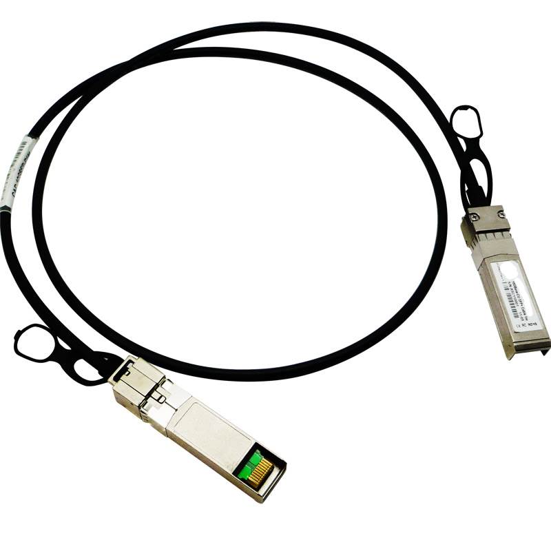
Twinaxial Cables (Data Center Specialists) In modern data centers, you will frequently encounter Twinax. A twinaxial cable consists of two inner copper conductors surrounded by a shared tubular insulating layer and a metallic shield. These are predominantly deployed as Direct Attach Copper (DAC) cables, which are factory-terminated twinaxial cables used for short-distance, high-speed data center connections. When you peer into a server rack, you will see DACs everywhere, because DAC cables typically connect network switches to nearby servers within the same physical equipment rack. They draw less power and introduce less latency than traditional twisted-pair cables.
When bandwidth requirements or distance limitations exceed the physical capacity of copper, we switch entirely to photons. Fiber optic cables transmit data via rapid pulses of light down microscopic strands of pure glass.
Single-Mode Fiber (SMF)
Single-mode fiber (SMF) optic cables use a laser as the internal light transmission source. Physically, they are microscopic. SMF optic cables typically have a glass core diameter between 8 and 10 microns—roughly a tenth the thickness of a human hair.
The Physics: The extremely narrow core of single-mode fiber effectively forces light pulses to travel in a single direct path without bouncing off the cladding walls.
Because the light travels straight without scattering, single-mode fiber supports significantly longer transmission distances than multimode fiber without experiencing severe signal degradation. In fact, SMF connections can span tens of kilometers without requiring a signal repeater, making it the primary medium for inter-city telecom backbones and campus-wide uplinks.
Multimode Fiber (MMF)
Conversely, multimode fiber (MMF) optic cables typically use Light Emitting Diodes (LEDs) or Vertical-Cavity Surface-Emitting Lasers (VCSELs) as the light source. To capture the less-focused light of an LED/VCSEL, the cable needs a wider aperture. MMF optic cables typically have a glass core diameter of 50 or 62.5 microns.
The Physics: The wider core of multimode fiber allows multiple light rays to propagate down the cable simultaneously at different reflection angles.
Imagine throwing a handful of bouncy balls down a wide hallway. The ones that bounce diagonally back and forth against the walls will arrive at the end slightly later than the ones thrown straight down the middle. This phenomenon is called modal dispersion. Because of this, modal dispersion in multimode fiber causes light pulses to spread out over distance and limits the maximum effective transmission range. Consequently, multimode fiber network connections are generally limited to transmission distances of less than 600 meters, making them ideal for backbone connections between closets inside the same building.
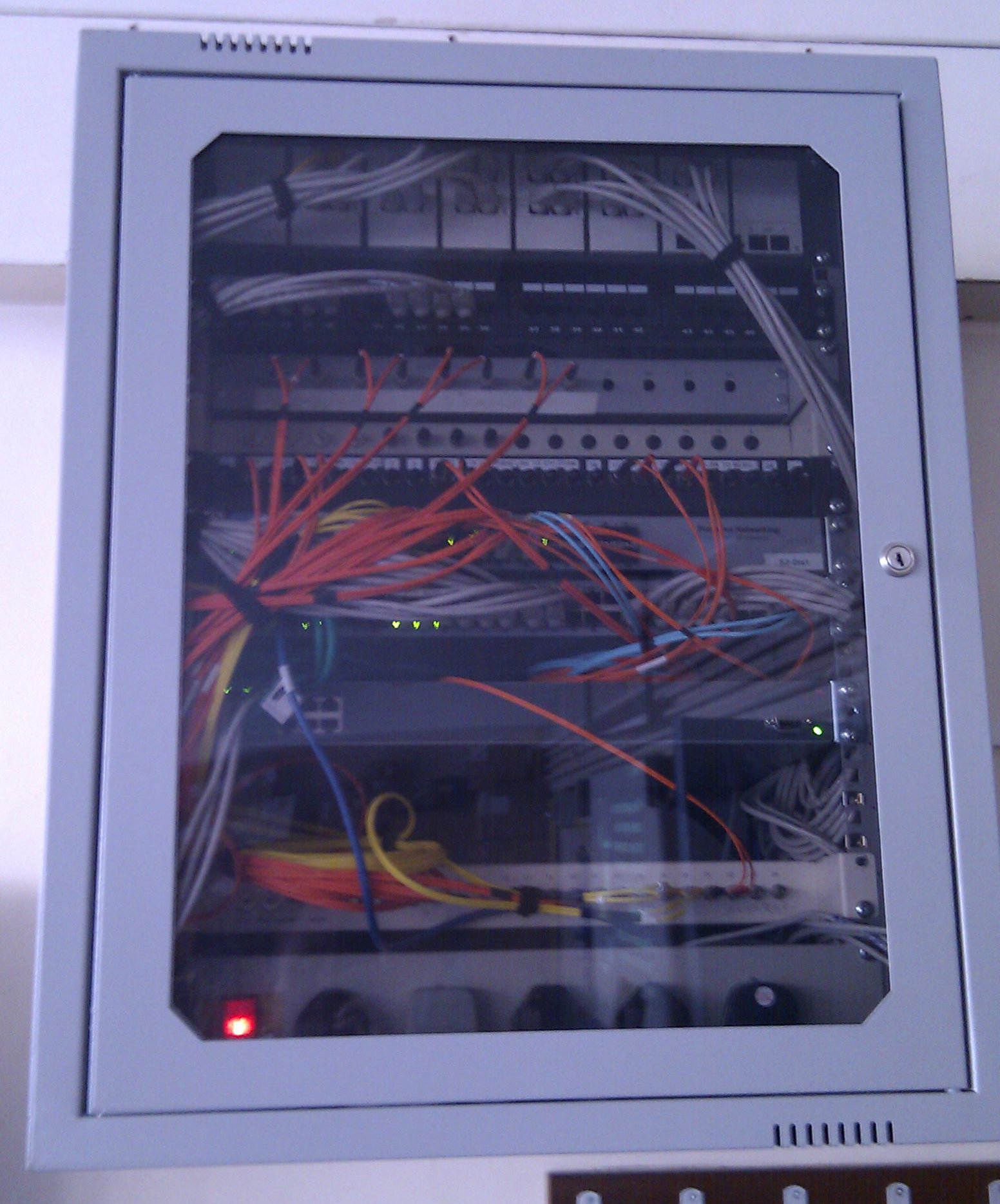
Networking is not just about moving data; it is about building safe infrastructure. The physical environment where you route your cables dictates the specific chemical makeup of the cable jackets you are legally allowed to install.
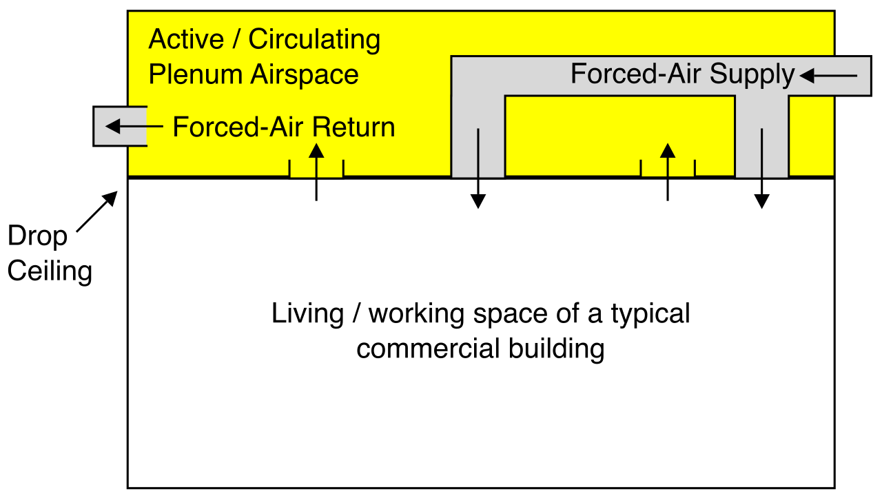
Commercial buildings utilize specific architectures to manage airflow. Plenum spaces are the structural areas within a building, such as drop ceilings or raised floors, used to circulate air for heating and cooling systems. If a fire breaks out, the air in these spaces—along with any smoke—is rapidly sucked into the HVAC system and distributed throughout the entire building.
The Hazard of PVC
Standard network cables—those you plug from a wall jack to a PC—are non-plenum. Non-plenum network cables typically have outer jackets made of Polyvinyl Chloride (PVC). While PVC is cheap and flexible, it is exceptionally dangerous in a fire. Polyvinyl Chloride (PVC) cable jackets release highly toxic fumes and heavy black smoke when burned. If PVC cables are placed in a drop ceiling, a small, localized fire will turn the HVAC system into a delivery mechanism for toxic gas.
Strict Fire Ratings
To prevent mass casualties during a building fire, building fire safety codes mandate the use of plenum-rated cables in any environmental air-handling spaces to prevent the rapid spread of toxic smoke.
- Plenum-rated network cables have jackets constructed from low-smoke materials like Fluorinated Ethylene Polymer (FEP) or Polytetrafluoroethylene (PTFE). These plastics do not easily burn, and when they do, they produce negligible smoke.
- Communications Multipurpose Plenum (CMP) is the official fire safety rating designation for plenum-grade network cables. If you are running cable above a drop ceiling, you must verify "CMP" is printed on the spool.
- Another rating you will see is CMR. Communications Multipurpose Riser (CMR) cables are specifically designed to prevent fire from spreading vertically up elevator shafts or between building floors. They have flame-retardant properties to prevent the cable itself from acting like a fuse between floors. However, riser-rated (CMR) cables are not certified to restrict toxic smoke emission and cannot legally be installed in plenum air spaces.
As an IT professional, recognizing the difference between these ratings is not merely a matter of network performance—it is a matter of life safety, regulatory compliance, and protecting your organization from massive liability.