Geometric Transformations
Not sure you’re ready?
Take the ~3-minute readiness diagnostic and see where you stand.
When a digital animator programs a character to move across a screen, or when an architect scales a blueprint to fit a tablet display, they are not manually redrawing shapes pixel by pixel. They are executing geometric transformations. A geometric transformation maps an original figure called a preimage onto a new figure called an image. For middle school mathematics teachers, mastering transformations is about building a bridge between pure geometry and algebraic functions. You are teaching students that space itself can be systematically manipulated, folded, and stretched using precise coordinate rules.
In the coordinate plane, we categorize these manipulations into two distinct families: those that preserve the absolute size and shape of a figure, and those that alter its proportions. Understanding the mechanical rules governing both is essential for leveraging on-screen graphing calculators and deciphering the complex multiple-choice and numeric-entry questions found on the Praxis 5164 exam.
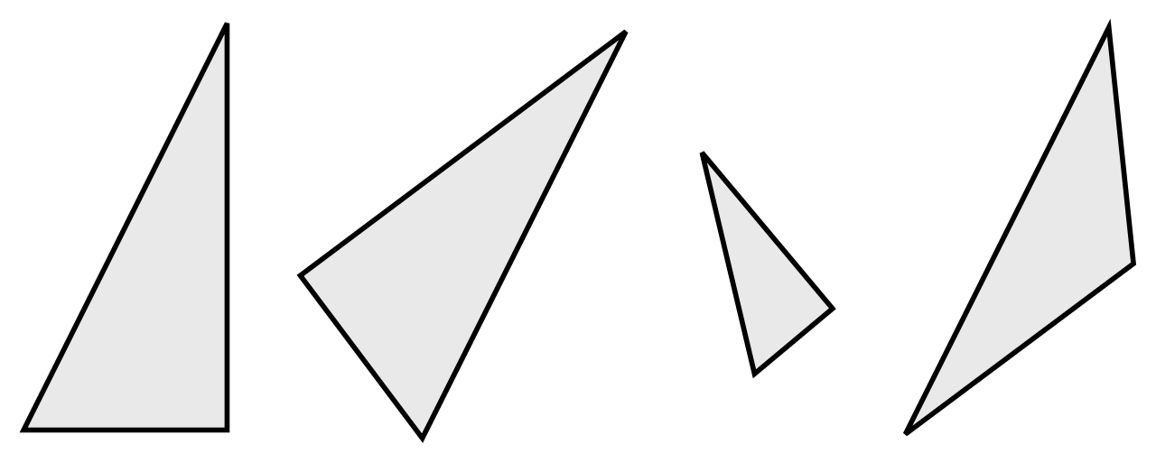
Imagine sliding a solid wooden triangle across a desk. No matter where you push it, flip it, or spin it, the physical properties of the wood do not change. Mathematically, this behavior defines a rigid transformation. Rigid geometric transformations are also referred to mathematically as isometries (from Greek isos meaning "equal" and metron meaning "measure").
A rigid transformation preserves the absolute distance between any two points on a geometric figure. Because side lengths remain constant, a rigid transformation also preserves the angle measures of a geometric figure. Furthermore, the internal structure of the shape remains unbroken: a rigid transformation preserves the collinearity of points from the preimage to the image (lines remain straight) and maps parallel lines on a preimage to parallel lines on the resulting image.
If you apply a sequence consisting solely of rigid transformations, it inherently maps a preimage to a geometrically congruent image. There are exactly three types of rigid transformations: translations, reflections, and rotations.
Translations: The Glide
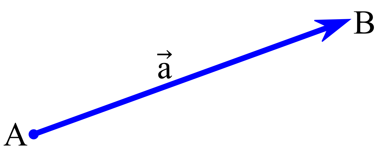
A translation is categorized as a rigid transformation. A translation slides a figure along a straight path without changing the orientation or size of the geometric figure.

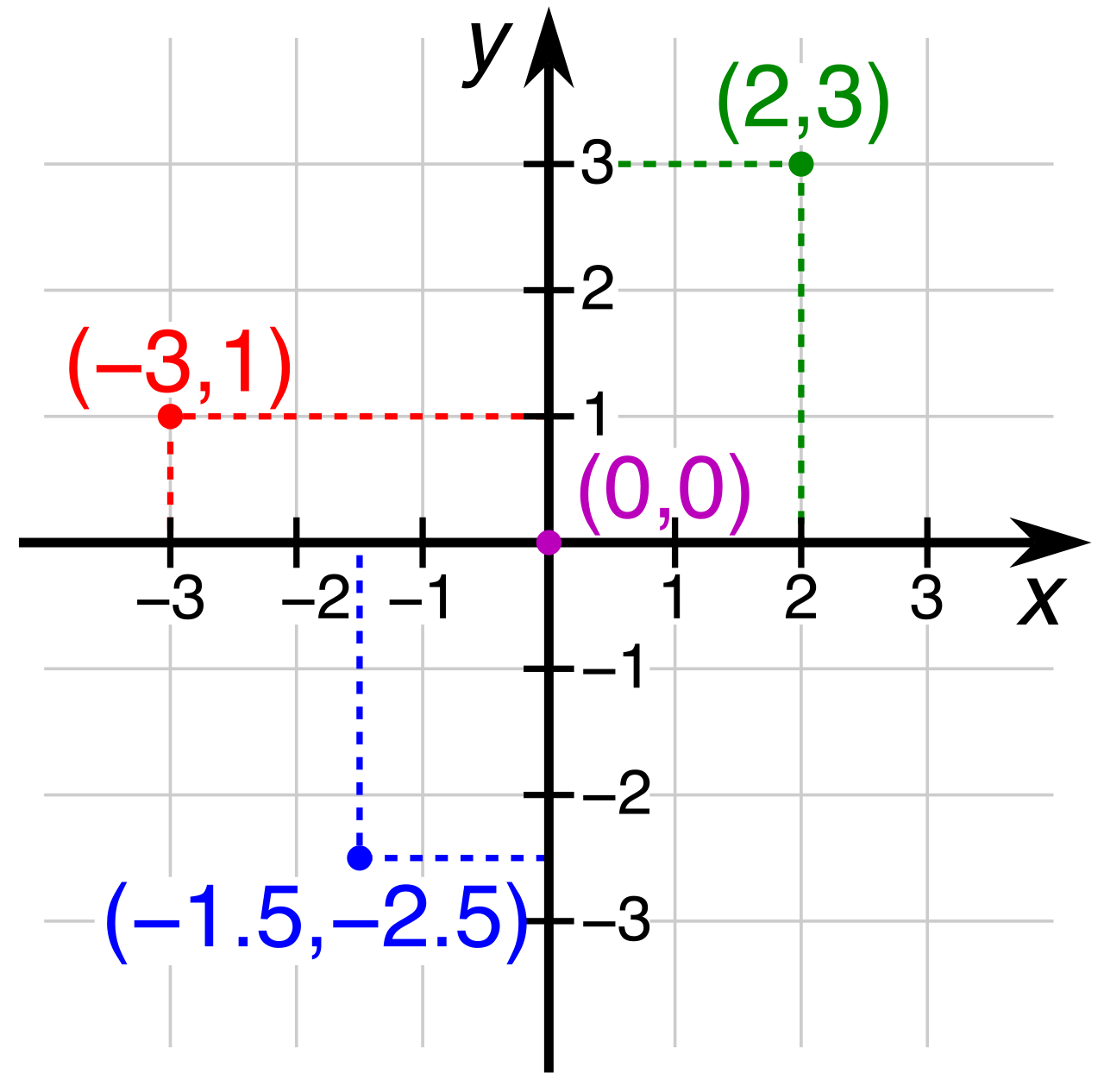
To tell a mathematical system exactly how to slide a figure, a translation is uniquely specified by a translation vector. A translation vector defines both the horizontal shift and the vertical shift applied to a preimage. When looking at a coordinate plane, we can express this algebraically: a translation by a units horizontally and b units vertically maps a coordinate point (x,y) to the point (x+a,y+b).
Because the figure simply glides across the plane, a translation preserves the geometric orientation of a polygon. Geometric orientation refers to the arrangement of points in a specific clockwise or counterclockwise sequence around a polygon perimeter. If the vertices A-B-C read clockwise before a translation, they will still read clockwise after.
Reflections: The Mirror
A reflection is also categorized as a rigid transformation, but it behaves entirely differently. A reflection flips a geometric figure across a specific line to create a mirror image. Consequently, a reflection transformation is uniquely specified by a single line of reflection.
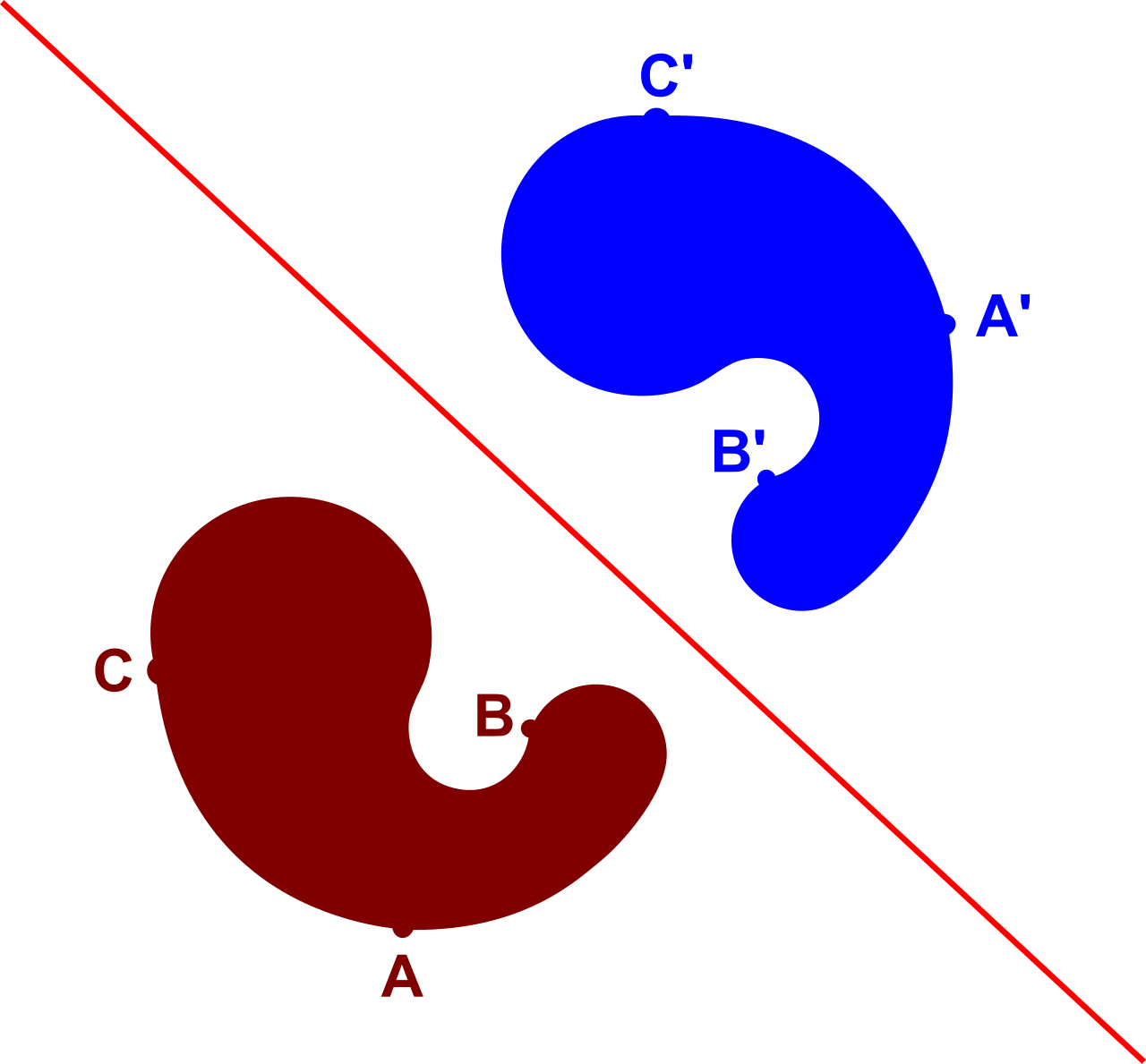
When you flip a figure, a profound geometric relationship emerges: a line of reflection acts as the exact perpendicular bisector of the segment connecting a preimage point to the corresponding image point. Any point located precisely on the line of reflection does not move at all; it acts as a fixed point during a reflection transformation. A fixed point is a coordinate location that maps to its exact original position after a geometric transformation.
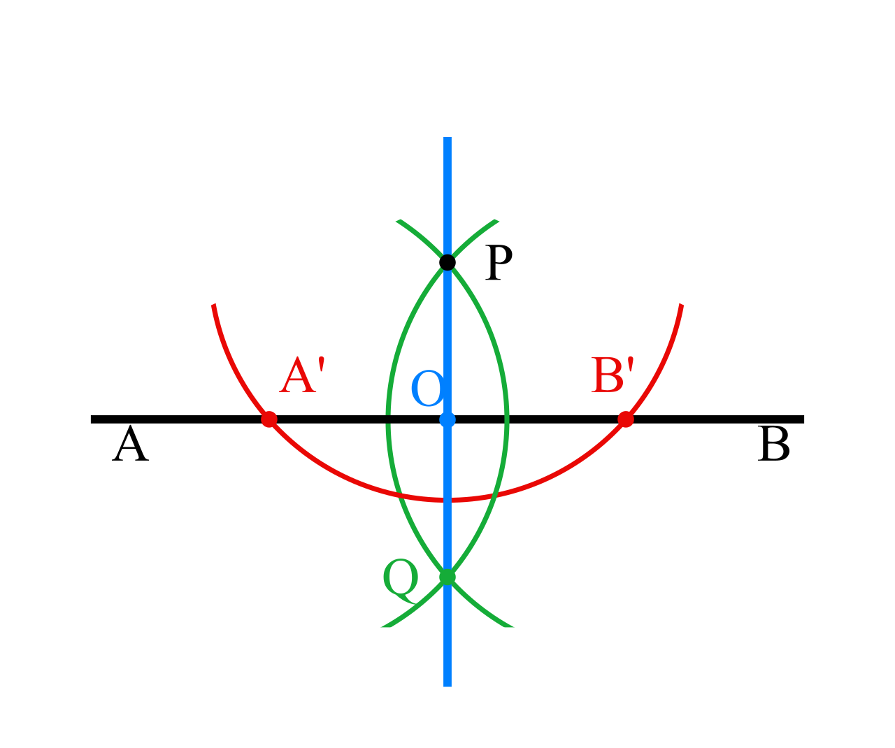
Unlike translations, a reflection reverses the geometric orientation of a polygon. If your preimage vertices are ordered clockwise, your reflected image vertices will be ordered counterclockwise.
For the Praxis exam, you must instantly recognize the algebraic rules for reflections across standard lines:
| Line of Reflection | Algebraic Mapping |
|---|---|
| x-axis | Maps (x,y) to (x,−y) |
| y-axis | Maps (x,y) to (−x,y) |
| Linear equation y=x | Maps (x,y) to (y,x) |
| Linear equation y=−x | Maps (x,y) to (−y,−x) |
| Origin (Point Reflection) | Maps (x,y) to (−x,−y) |
Note: A point reflection across the origin is essentially flipping the point across both axes simultaneously.
Rotations: The Turn
The third isometry is the rotation, which is categorized as a rigid transformation. A rotation turns a geometric figure around a fixed point by a specific angle measurement. Therefore, a rotation transformation is specified by a center of rotation, an angle of rotation, and a direction of rotation.
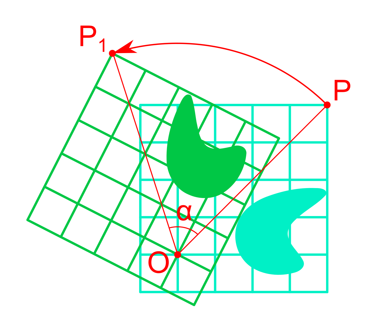
Like a translation, a rotation preserves the geometric orientation of a polygon. The exact center of rotation acts as a fixed point during a rotation transformation.
In the Cartesian coordinate system, we abide by standard directional conventions:
- A positive angle of rotation in the coordinate plane dictates a counterclockwise turning direction.
- A negative angle of rotation in the coordinate plane dictates a clockwise turning direction.
Rotating a figure 90 degrees clockwise produces identical coordinates to a rotation of 270 degrees counterclockwise. Standard coordinate mappings for rotations about the origin (0,0) are vital:
- 90∘ counterclockwise: Maps (x,y) to (−y,x)
- 180∘: Maps (x,y) to (−x,−y) (Notice this is algebraically identical to a point reflection across the origin).
- 270∘ counterclockwise: Maps (x,y) to (y,−x)
Locating the Unseen Center of Rotation
Exam questions often present a preimage and a rotated image and ask you to find the center of rotation. Recall that the geometric center of rotation lies exactly on the perpendicular bisector of every segment connecting a preimage point to the corresponding rotated image point. Therefore, to find the center, simply draw segments connecting two pairs of corresponding points. The intersection coordinate of two perpendicular bisectors of segments connecting preimage points to corresponding rotated image points reveals the exact center of rotation.
We now leave the rigid world of isometries. A dilation is a non-rigid transformation that changes the overall size of a geometric figure. Even though the size changes, the fundamental architecture of the shape does not collapse. A dilation preserves the proportional shape and angle measures of a geometric figure. It also preserves the collinearity of points from the preimage to the resulting image, and maps parallel lines on a preimage to parallel lines on the resulting image. Furthermore, like translations and rotations, a dilation preserves the geometric orientation of a polygon.

A dilation transformation is specified by two elements: a center of dilation and a numerical scale factor. The exact center of dilation acts as a fixed point during a dilation transformation.
The scale factor of a dilation is the ratio of a side length of the image to the corresponding side length of the preimage. The mathematical relationship is multiplicative, not additive. The distance between any two points on a dilated image equals the corresponding preimage distance multiplied by the absolute value of the scale factor.
If the center of dilation is the origin (0,0), a dilation with a scale factor of k maps a coordinate point (x,y) to the point (kx,ky).
The Scale Factor Spectrum
The numerical value of k dictates the nature of the dilation:
- A dilation produces an enlargement of the preimage if the absolute value of the scale factor is strictly greater than one (∣k∣>1).
- A dilation produces a reduction of the preimage if the absolute value of the scale factor is strictly between zero and one (0<∣k∣<1).
- A dilation with a scale factor of exactly one maps the preimage onto identical image coordinates.
- Crucially: A dilation with a negative scale factor produces an image that is rotated 180 degrees around the center of dilation relative to the preimage. It essentially pulls the figure entirely through the center point and out the other side.
Dilations and Infinite Lines
When dilating lines themselves, an elegant geometric rule applies. A dilation maps a line not passing through the center of dilation to a strictly parallel line. Conversely, a dilation maps a line passing through the center of dilation directly onto that exact same line.
If you are given a preimage and its dilated image and asked to find the center of dilation, simply draw lines connecting corresponding vertices. Straight lines connecting corresponding vertices on a dilated preimage and its image will always intersect at the specific center of dilation.
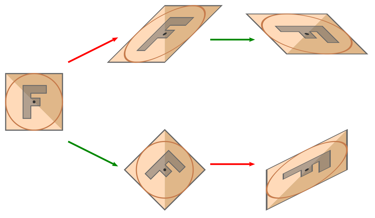
In a graphing calculator or animation software, transformations rarely happen in isolation. The composition of geometric transformations involves the successive mathematical application of two or more transformations.
The Golden Warning of Composition: The composition of geometric transformations is fundamentally not a commutative mathematical operation.
If you translate a square up, then rotate it 90 degrees around the origin, it will land in a completely different spot than if you rotate it 90 degrees first, then translate it up. Reversing the execution order of transformations in a composition sequence frequently alters the final coordinate positions of the image.
When evaluating the end result of a composition sequence:
- A sequence consisting solely of rigid transformations maps a preimage to a geometrically congruent image.
- A sequence of transformations containing at least one dilation produces an image that is geometrically similar to the preimage (same angles, proportional sides).
The Double Reflection Phenomena
Reflecting a figure twice creates fascinating composite shortcuts that frequently appear on certification exams:
- Across Parallel Lines: The composition of two separate reflections across parallel lines is mathematically equivalent to a single translation. The overall distance of the translation resulting from two reflections across parallel lines is exactly twice the distance separating the parallel lines.
- Across Intersecting Lines: The composition of two separate reflections across intersecting lines is mathematically equivalent to a single rotation. The specific angle of the rotation resulting from two reflections across intersecting lines is exactly twice the angle formed between the intersecting lines.
When you are looking at a messy coordinate plane featuring a preimage and a final image, how do you mathematically reverse-engineer what happened?
First, look at the geometric orientation. Comparing the orientation of a preimage and an image helps mathematically identify the presence of a reflection in a transformation sequence.
- An image demonstrating reversed orientation relative to the preimage indicates that an odd number of reflections occurred in the overall transformation sequence (1, 3, 5, etc.).
- An image demonstrating identical orientation relative to the preimage indicates that an even number of reflections occurred in the overall transformation sequence (0, 2, 4, etc.).
Finally, if you need to build a formula mapping a preimage to its image, you do not need every single point on the polygon. Three non-collinear preimage points and their corresponding image points are entirely sufficient to uniquely determine a two-dimensional rigid transformation. By tracking just three vertices—the vertices of a single triangle—you lock down the exact algebraic movement of the entire infinite plane.
As you step into the classroom, remember that teaching geometric transformations is teaching students the foundational operating system of modern digital graphics, physics, and engineering. The coordinate plane is not just a static grid; it is a canvas waiting for mathematical instruction.